
Valve Clearance - Checking / Adjusting
EM-46prose procedureChecking
IMPORTANT
Check valve clearance while engine is warm and not running.
Checking
- 1Remove rocker cover.
- 2Remove all spark plugs.
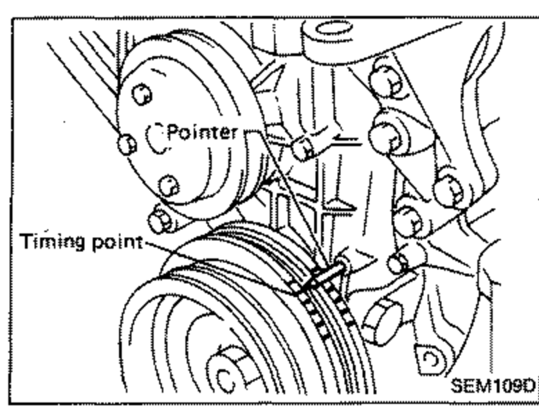
- 3Set No. 1 cylinder at T.D.C. on its compression stroke.Align pointer with T.D.C. mark on crankshaft pulley.
 SEM108D
 - 4Check that valve lifters on No. 1 cylinder are loose and valve lifters on No. 4 are tight.If not, turn crankshaft one revolution (360°) and align as above.
 SEM136D
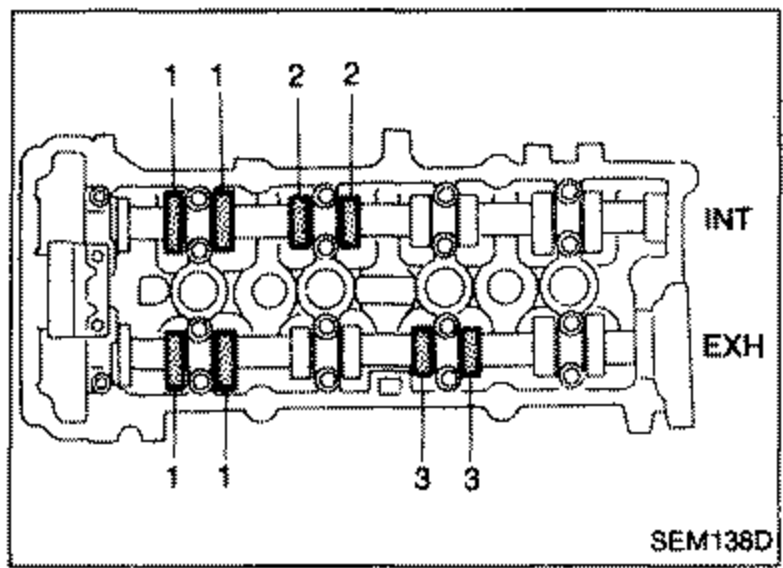
 - 5Check only those valves shown in the figure. Using a feeler gauge, measure clearance between valve lifter and camshaft. Record any valve clearance measurements which are out of specification. They will be used later to determine the required replacement adjusting shim.
 SEM109D
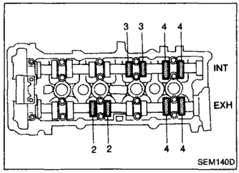
 - 6Turn crankshaft one revolution (360°) and align mark on crankshaft pulley with pointer. Check those valves shown in the figure. Use the same procedure as mentioned in step 4.
 SEM140D
 - 7If all valve clearances are within specification, install the following parts: Rocker cover; All spark plugs.
| Specification | Value |
|---|---|
| Intake0.008 - 0.019 in | 0.21 - 0.49mm |
| Exhaust0.012 - 0.023 in | 0.30 - 0.58mm |
Intake0.008 - 0.019 in
0.21 - 0.49mm
Exhaust0.012 - 0.023 in
0.30 - 0.58mm
Adjusting
IMPORTANT
Adjust valve clearance while engine is cold.
Adjusting
- 1Turn crankshaft to position cam lobe on camshaft of valve being adjusted upward.
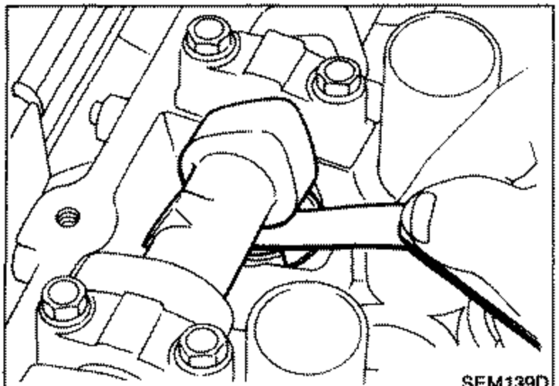
- 2Place Tool (A) around camshaft as shown in figure. Before placing Tool (A), rotate notch toward center of cylinder head (See figure.), to simplify shim removal later.Be careful not to damage cam surface with Tool (A).
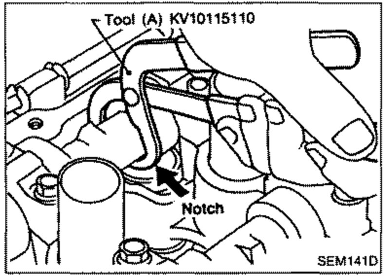 SEM141D