
Cylinder Head - Inspection
EM-219prose procedureNominal cylinder head height given for CD17. CD engine inspection.
CYLINDER HEAD — Inspection
Cylinder Head Distortion
- 1Visually check for cracks and deformation.
- 2Check cylinder head for distortion. Head surface flatness: Less than 0.1 mm (0.004 in). If beyond the specified limit, replace or resurface cylinder head.
IMPORTANT
Resurfacing limit:
The resurfacing limit of the cylinder head is related to the amount of resurfacing of the cylinder block. When:
"A" is the amount of resurfacing needed for the cylinder head and "B" is the amount of resurfacing needed for the cylinder block, the maximum limit is determined by
A + B = 0.1 mm (0.004 in)
After resurfacing cylinder head, check that camshaft rotates freely by hand. If resistance is felt, the cylinder head must be replaced.
| Specification | Value |
|---|---|
| Head surface flatness0.004 in | Less than 0.1mm |
| Resurfacing limit (A + B)0.004 in | 0.1mm |
| Nominal height of cylinder headCD17; 4.591 - 4.606 in | 116.6 - 117.0mm |
Head surface flatness0.004 in
Less than 0.1mm
Resurfacing limit (A + B)0.004 in
0.1mm
Nominal height of cylinder headCD17; 4.591 - 4.606 in
116.6 - 117.0mm
Valve Guide Clearance
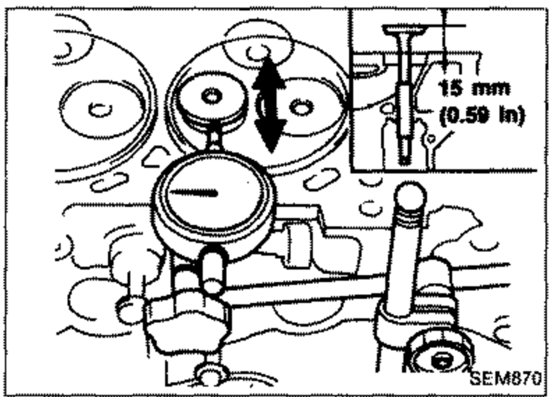
- 1Measure deflection across the cylinder head as illustrated. Valve deflection limit (dial gauge reading): 0.1 mm (0.004 in)
 SEM870
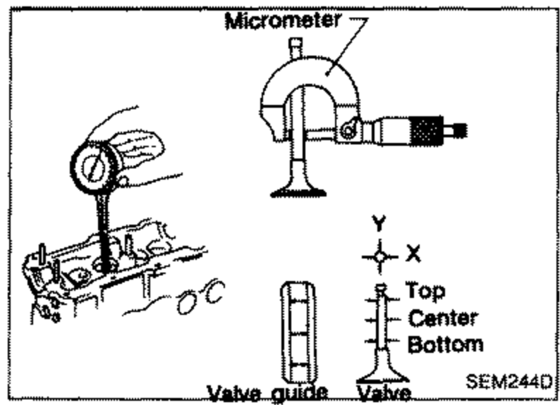
 - 2If exceeding the limit, check valve-to-guide clearance.a) Measure valve stem diameter and valve guide inner diameter as illustrated.b) Check that clearance is within the specification. Valve stem to valve guide clearance limit: 0.1 mm (0.004 in)c) If exceeding the limit, replace valve or valve guide.
 SEM244D
Valve Guide Replacement
- 1Heat cylinder head in oil to 150 to 160°C (300 to 320°F).
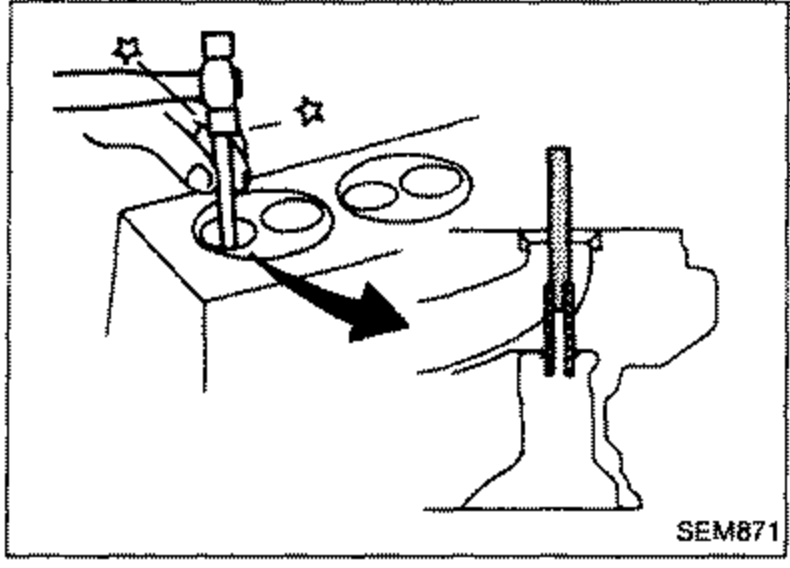
- 2Drive out valve guide using a press or hammer and a suitable tool.
 SEM871