
Cylinder Head - Assembly (Cont'd)
EM-121prose procedureIntake manifold tightening sequence differs between SR20DE and SR20DET. Exhaust manifold and its cover installation is SR20DE only. Valve identification marks differ by engine.
Assembly (Cont'd)
- 3Install water outlet.(1) Before installing water outlet, remove all traces of liquid gasket from mating surface using a scraper. Also remove traces of liquid gasket from mating surface of cylinder head.(2) Apply a continuous bead of liquid gasket to mating surface of water outlet.Use Genuine Liquid Gasket or equivalent.
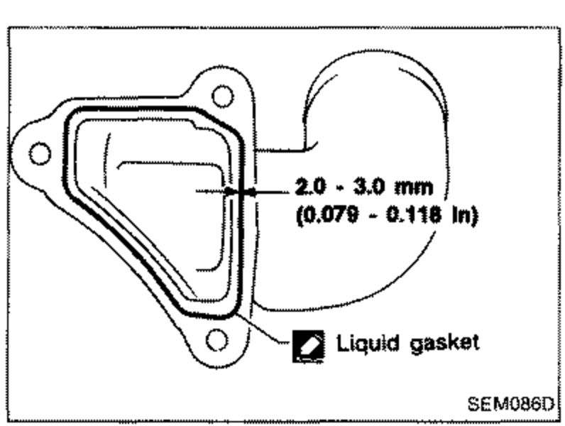 SEM086D
 - 4Install intake manifold. Refer to "Installation" in "INTAKE MANIFOLD".
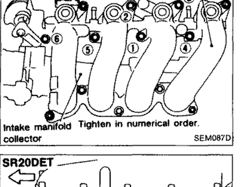 SEM087D
 - 5Install exhaust manifold. (SR20DE only)
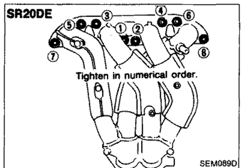 SEM089D
 - 6Install exhaust manifold cover. (SR20DE only)
- 7Install valve component parts.Install valves, noting their identification marks as indicated in the table below.
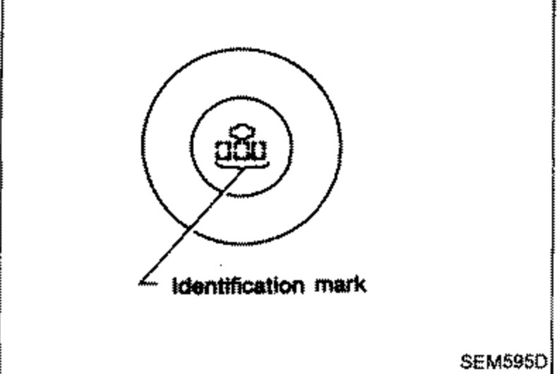 SEM595O
Valve identification mark
Intake valve
SR20DE53J
SR20DET54C
Exhaust valve
SR20DE5J
SR20DET5C or no mark
See also
INTAKE MANIFOLD