
ENGINE REMOVAL
EM-234prose procedureCD engine. Continuation of engine removal procedure (steps 15-20). L.H./R.H. drive shaft removal differs: RH splits drive shaft center thrust bearing. Section tab marked 'CD'.
Engine Removal (continued)
- 15Remove brake caliper mounting bolts and bind caliper properly to vehicle (coil spring) L.H. & R.H.
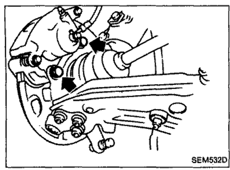 SEM532D
 - 16Remove lower ball joint nuts and release the upper hub mounting bolts.
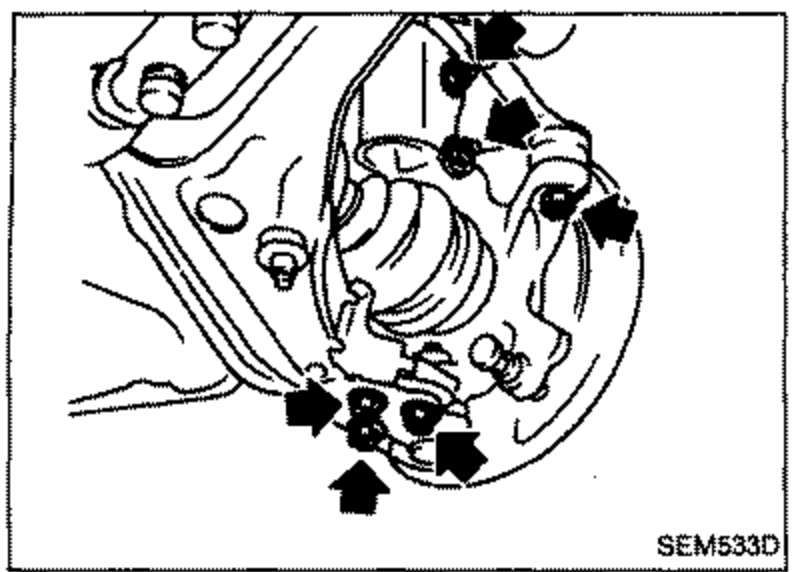 SEM533D
 - 17Release steering arm ball joint using a suitable tool. Remove drive shafts from transaxle.1) RH: Split drive shaft center thrust bearing.2) RH & LH: Remove hub mounting bolts and remove drive shaft carefully from transaxle.
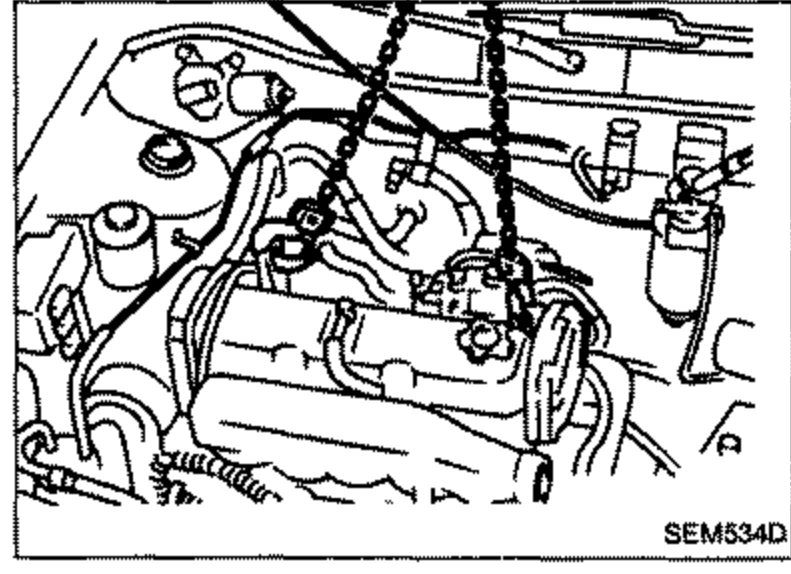
- 18Mount suitable slingers to cylinder head. Fit hoist with studge and hoist engine to release force on engine mountings.
 SEM534D
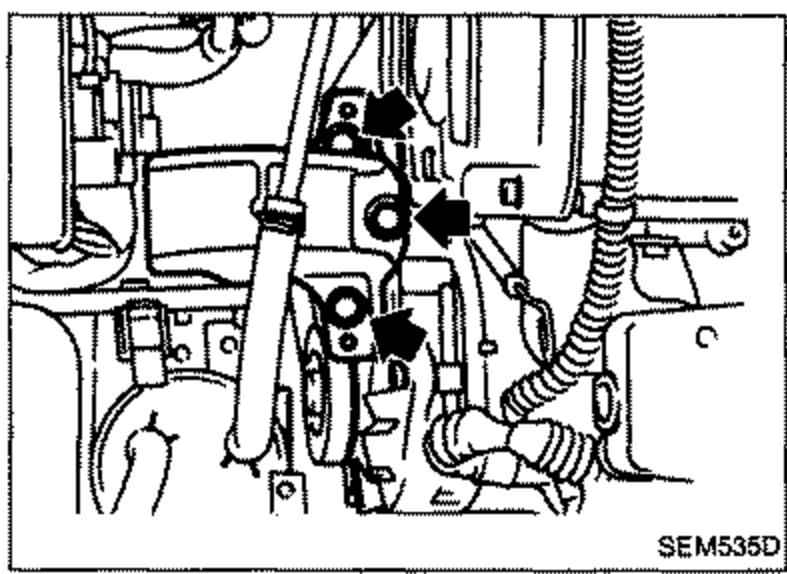
 - 19Remove upper mounting (Right side).
 SEM535D
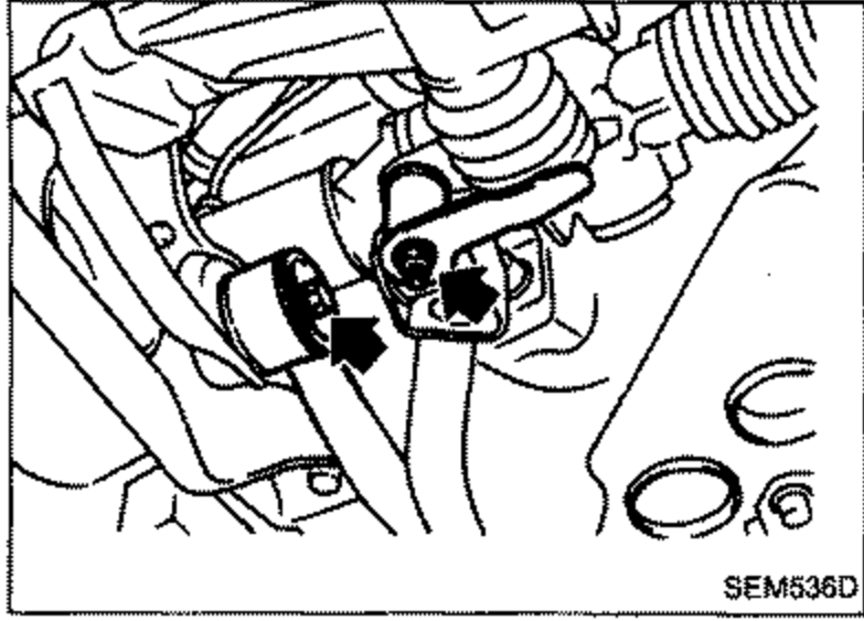
 - 20Release transaxle shift linkages.
 SEM536D