
Cylinder Block - Assembly (Cont'd)
EM-154prose procedureCrankshaft bearing cap bolt tightening torques differ between SR20DE and SR20DET.
Assembly (Cont'd)
Crankshaft
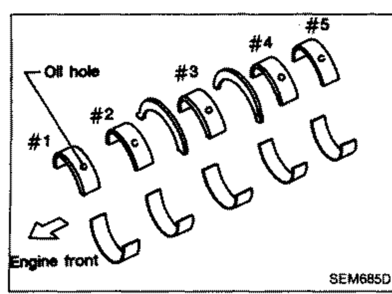
- 1Set main bearings in their proper positions on cylinder block and main bearing cap.Confirm that correct main bearings are used. Refer to "Inspection" of this section.
 SEM685D
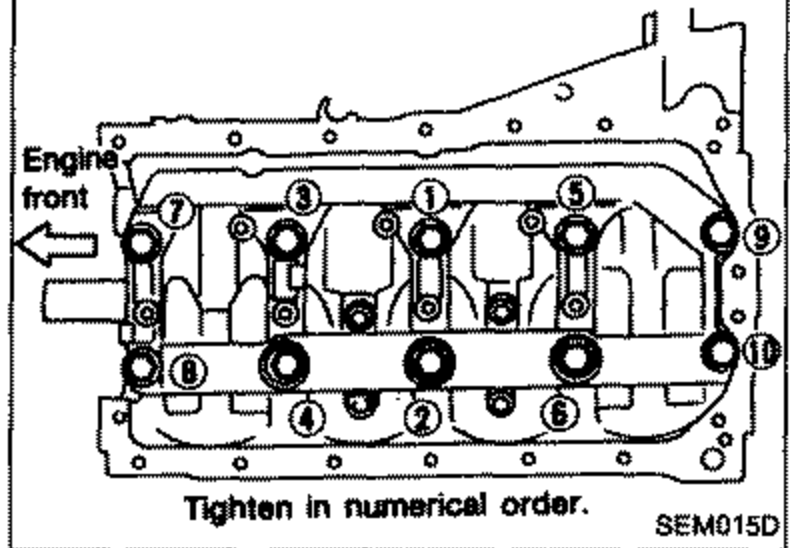
 - 2Install crankshaft, main bearing caps and beam and tighten bolts to the specified torque.Prior to tightening bearing cap bolts, place bearing cap in its proper position by shifting crankshaft in the axial direction.Tightening procedure (SR20DE): 1) Tighten bolts to 32 to 38 N-m (3.3 to 3.9 kg-m, 24 to 28 ft-lb). 2) Turn bolts 45 to 50 degrees clockwise or if angle wrench is not available, tighten bolts to 73 to 82 N-m (7.4 to 8.4 kg-m, 54 to 61 ft-lb).Tightening procedure (SR20DET): 1) Tighten bolts to 38 to 44 N-m (3.9 to 4.5 kg-m, 28 to 33 ft-lb). 2) Turn bolts 60 to 65 degrees clockwise or if angle wrench is not available, tighten bolts to 84 to 114 N-m (8.6 to 11.6 kg-m, 62 to 84 ft-lb).After securing bearing cap bolts, make sure crankshaft turns smoothly by hand.
 SEM015D
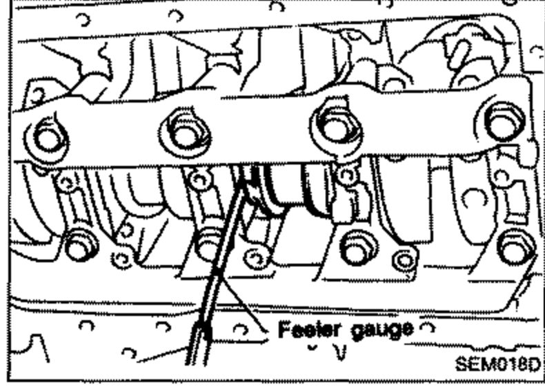
 - 3Measure crankshaft end play.Crankshaft end play: Standard 0.10 - 0.26 mm (0.0039 - 0.0102 in), Limit 0.30 mm (0.0118 in)If beyond the limit, replace thrust bearings with new ones.
 SEM018D
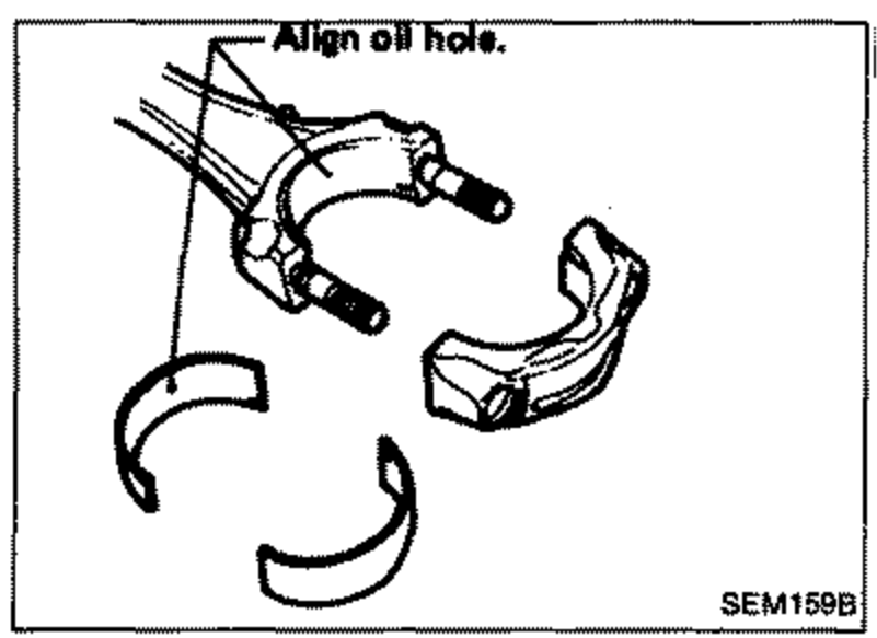
 - 4Install connecting rod bearings in connecting rods and connecting rod caps.Confirm that correct bearings are used. Refer to "Inspection".Install bearings so that oil hole in connecting rod aligns with oil hole of bearing.
 SEM159B