
Cylinder Head - Inspection (Cont'd)
EM-117prose procedureInspection (Cont'd)
Valve Guide Replacement (Cont'd)
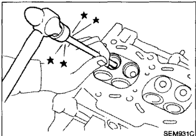
- 2Press out valve guide or use a hammer and suitable tool.
 SEM931C
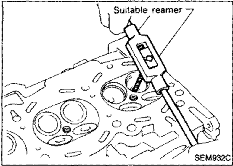
 - 3Ream cylinder head valve guide hole. Valve guide hole diameter (for service parts): Intake 10.175 - 10.196 mm (0.4006 - 0.4014 in); Exhaust 11.175 - 11.196 mm (0.4400 - 0.4408 in)
 SEM932C
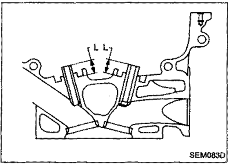
 - 4Heat cylinder head to 110 to 130 degrees C (230 to 266 degrees F) and press service valve guide onto cylinder head. Projection "L": 14.0 - 14.2 mm (0.551 - 0.559 in)
 SEM083D
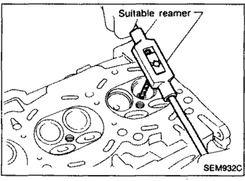
 - 5Ream valve guide. Valve guide inner diameter: Intake 6.000 - 6.018 mm (0.2362 - 0.2369 in); Exhaust 7.000 - 7.018 mm (0.2756 - 0.2763 in)
 SEM932C
VALVE SEATS
Check valve seats for any evidence of pitting at valve contact surface, and reset or replace if it has worn out excessively.
IMPORTANT
Before repairing valve seats, check valve and valve guide for wear. If they have worn, replace them. Then correct valve seat.
Cut with both hands to uniform the cutting surface.