
Valve Clearance Adjustment (Cont'd)
EM-125prose procedureSR (SR20DE/SR20DET) engine cylinder head.
Valve Clearance Adjustment (Cont'd)
- 3Set No. 1 piston at T.D.C. on the compression stroke by rotating crankshaft.
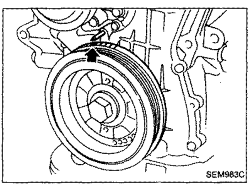 SEM983C
IMPORTANT
Rotate crankshaft until mating mark on camshaft sprocket is set at position indicated in figure at left.
Valve Clearance Adjustment (Cont'd)
- 4Check only those camshaft clearances shown in the figure.
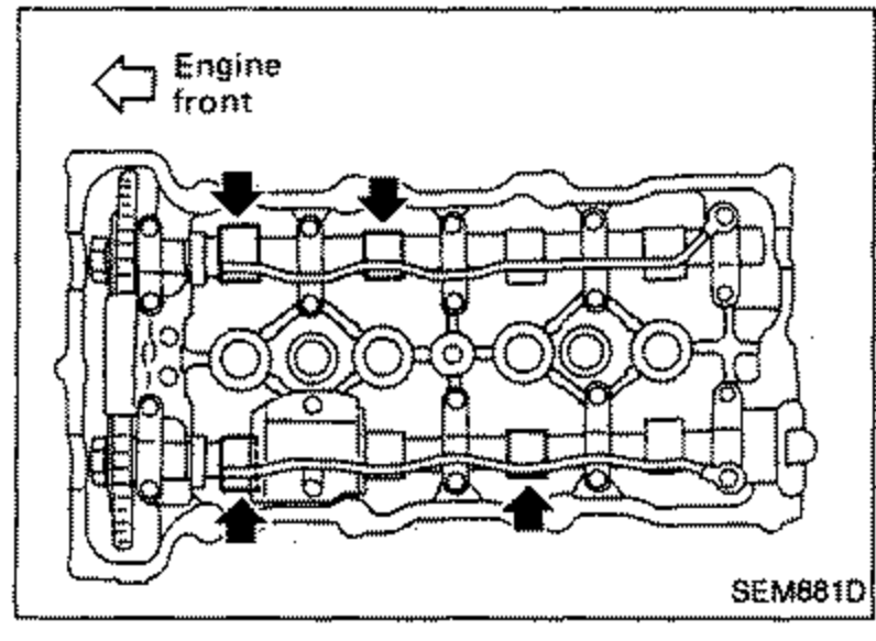 SEM681D
Feeler gauge measurement
- 1Using *two feeler gauges (with one placed on the other), measure the camshaft-to-rocker arm clearance at two places (one on the shim side and one on the rocker arm guide side). Be sure to insert the gauges horizontally.*: To minimize the measuring error.One feeler gauge increases the measurement error because the gauge is too stiff to bend.More than two gauges increases the gauge error twice as much, resulting in a considerable measurement error.
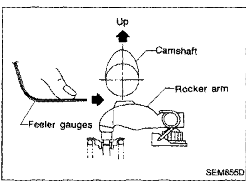 SEM855D
 - 2Record any valve clearance measurements which are out of specification. They will be used later to determine the required replacement adjusting shim.
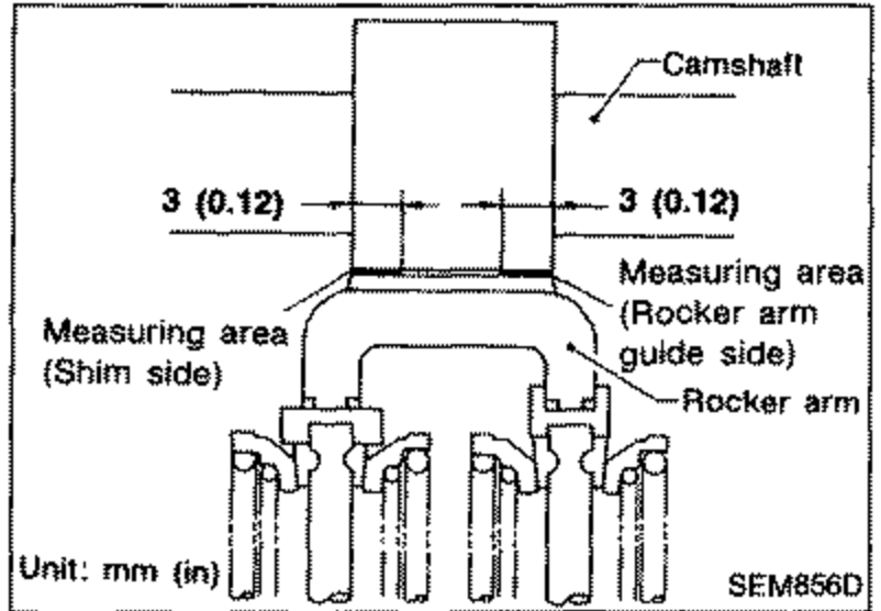 SEM856D
| Specification | Value |
|---|---|
| Camshaft clearance (Hot): Intake & ExhaustHot | 0.20 - 0.23mm0.0079 - 0.0091in |
Camshaft clearance (Hot): Intake & ExhaustHot
0.20 - 0.23mm0.0079 - 0.0091in