
Cylinder Head - Inspection (Valve Dimensions, Springs, Lifter)
EM-222prose procedureCD17 uses mechanical valve lifter; CD20 uses hydraulic valve lifter.
CYLINDER HEAD — Inspection
Valve Dimensions
- 1Check dimensions of each valve. For dimensions, refer to S.D.S.
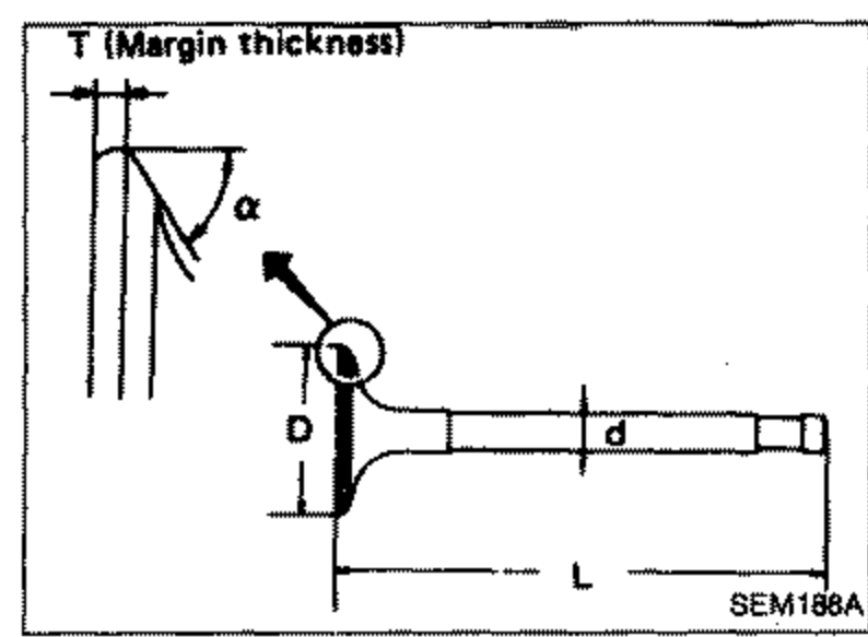 SEM188A
 - 2Correct or replace any valve that is faulty.
- 3Valve face or valve stem end surface should be refaced by using a valve grinder.When valve head has been worn down to 0.5 mm (0.020 in) in margin thickness, replace the valve.Grinding allowance for valve stem tip is 0.5 mm (0.020 in) or less.
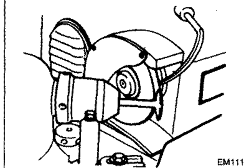 EM111
EM111
VALVE SPRING SQUARENESS
Check valve spring for squareness using a steel square and flat surface plate. If spring is out of square "S" more than specified limit, replace with new one.
| Specification | Value |
|---|---|
| Out-of-square, Outer0.083 in | Less than 2.1mm |
| Out-of-square, Inner0.075 in | Less than 1.9mm |
Out-of-square, Outer0.083 in
Less than 2.1mm
Out-of-square, Inner0.075 in
Less than 1.9mm
VALVE SPRING PRESSURE LOAD
Measure the free length and the tension of each spring. If the measured value exceeds the specified limit, replace spring. Refer to S.D.S.
VALVE LIFTER
NOTE
CD17: Valve lifter
CD20: Hydraulic valve lifter
Valve Lifter
- 1Check contact and sliding surfaces for wear or scratches.
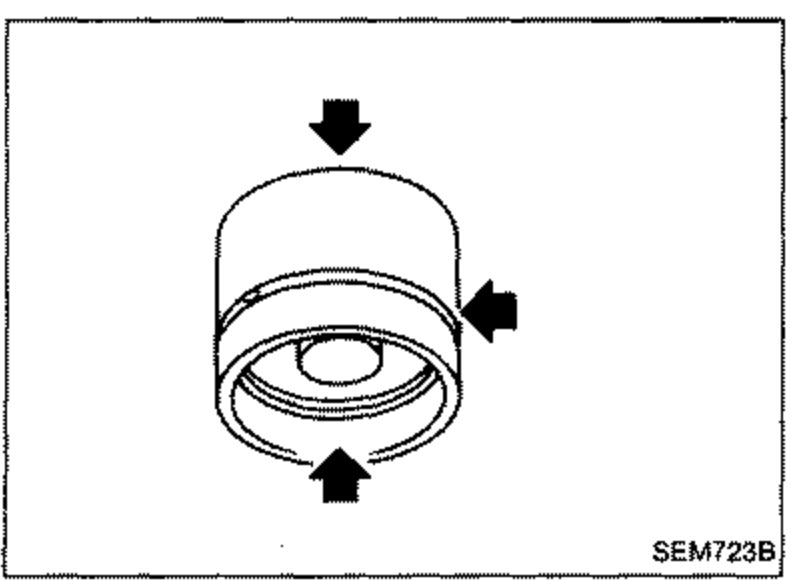 SEM723B
See also
S.D.S.