
Cylinder Head - Inspection (Valve Seat Replacement)
EM-221prose procedureValve seat reaming bores differ between CD17 and CD20.
CYLINDER HEAD — Inspection
Valve Seat Replacement
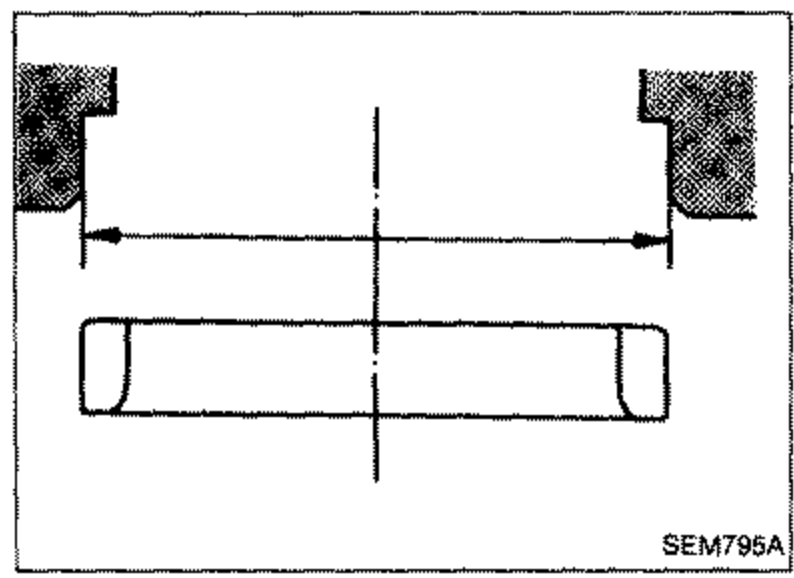
- 1Bore out old seat until it collapses. The machine depth stop should be set so that boring cannot continue beyond the bottom face of the seat recess in cylinder head.
 SEM795A
 - 2Ream the cylinder head recess. Reaming bore for service valve seat [Oversize 0.5 mm (0.020 in)]: CD17 — Intake 38.44 ± 0.01 mm (1.5134 ± 0.0004 in), Exhaust 34.46 ± 0.01 mm (1.3567 ± 0.0004 in); CD20 — Intake 40.943 ± 0.011 mm (1.6119 ± 0.0004 in), Exhaust 34.943 ± 0.011 mm (1.3757 ± 0.0004 in).Reaming should be done to the concentric circles around the valve guide center so that valve seat will have the correct fit.
- 3Heat cylinder head to a temperature of 150 to 160°C (302 to 320°F) and press fit seat until it seats on the bottom.
- 4Install valve seats.When replacing valve seat, valve should be replaced as well.
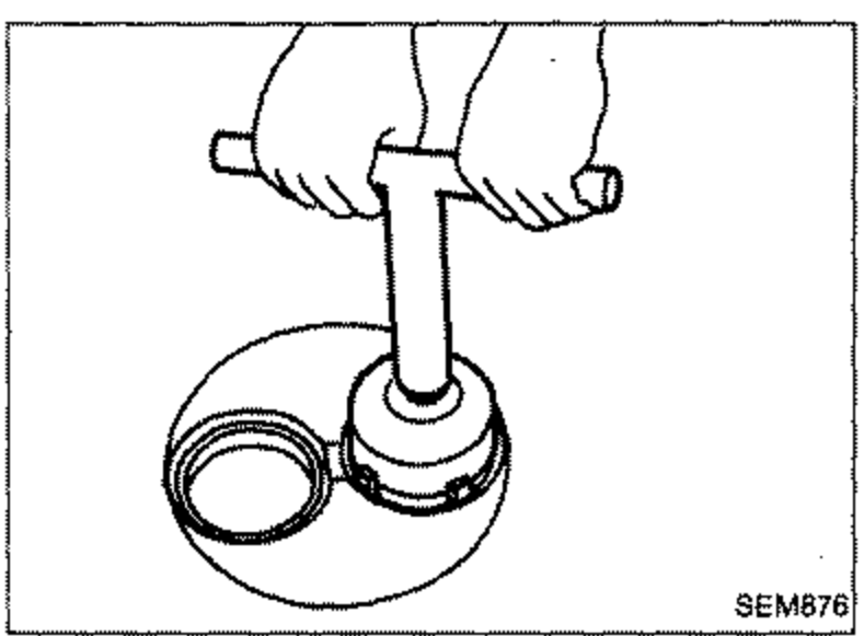
- 5Cut or grind valve seat using a suitable tool at the specified dimensions as shown in S.D.S.The cutting should be done with both hands to obtain a uniform and concentric finish.
 SEM876
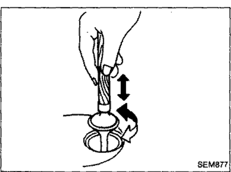
 - 6Apply a small amount of fine grinding compound to the valve's contacting face and put the valve into its guide. Lap valve against its seat until proper valve seating is obtained.
 SEM877
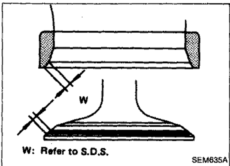
 - 7Check valve seating condition.
 SEM635A
| Specification | Value |
|---|---|
| Reaming bore for service valve seat (oversize 0.5 mm / 0.020 in), CD17 Intake1.5134 ± 0.0004 in | 38.44 ± 0.01mm |
| CD17 Exhaust1.3567 ± 0.0004 in | 34.46 ± 0.01mm |
| CD20 Intake1.6119 ± 0.0004 in | 40.943 ± 0.011mm |
| CD20 Exhaust1.3757 ± 0.0004 in | 34.943 ± 0.011mm |
Reaming bore for service valve seat (oversize 0.5 mm / 0.020 in), CD17 Intake1.5134 ± 0.0004 in
38.44 ± 0.01mm
CD17 Exhaust1.3567 ± 0.0004 in
34.46 ± 0.01mm
CD20 Intake1.6119 ± 0.0004 in
40.943 ± 0.011mm
CD20 Exhaust1.3757 ± 0.0004 in
34.943 ± 0.011mm
See also
S.D.S.