
Cylinder Head - Inspection (Valve Seats)
EM-220prose procedureValve guide protrusion differs: CD17 13.8 mm vs CD20 10.3 mm.
CYLINDER HEAD — Inspection
Valve Guide Replacement (continued)
- 3Ream cylinder head valve guide bore. Reaming bore (service part): 11.185 - 11.196 mm (0.4404 - 0.4408 in)
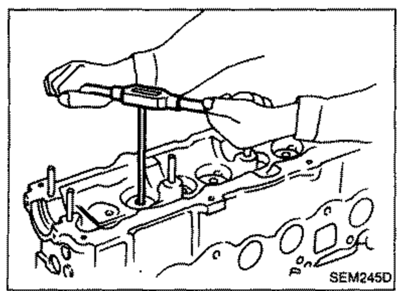 SEM245D
 - 4Heat cylinder head to 150 to 160°C (302 to 320°F) and press service valve guide onto cylinder head.
- 5Ream valve guide. Final size: 7.000 - 7.015 mm (0.2756 - 0.2762 in)
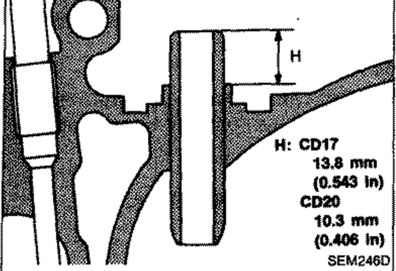 SEM246D
| Specification | Value |
|---|---|
| Reaming bore (service part)0.4404 - 0.4408 in | 11.185 - 11.196mm |
| Final size (valve guide)0.2756 - 0.2762 in | 7.000 - 7.015mm |
| Valve guide protrusion HCD17; 0.543 in | 13.8mm |
| Valve guide protrusion HCD20; 0.406 in | 10.3mm |
Reaming bore (service part)0.4404 - 0.4408 in
11.185 - 11.196mm
Final size (valve guide)0.2756 - 0.2762 in
7.000 - 7.015mm
Valve guide protrusion HCD17; 0.543 in
13.8mm
Valve guide protrusion HCD20; 0.406 in
10.3mm
Valve Seats
- 1Check valve and valve seat for contact. Coat the valve face with prussian red lead. If contact is wrong, correct valve seat. If the valve red lead appears 360° around face, the valve stem and face are concentric. If not, repair or replace valve.
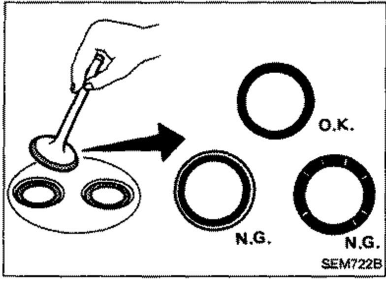 SEM722B
 - 2Check valve seats for any evidence of pitting on valve contact surface, and reseat or replace if worn out excessively. Correct valve seat surface.When repairing valve seat, check valve and valve guide for wear beforehand. If worn, replace them. Then correct valve seat.