
Parts Diagrams
Exploded views and component parts lists from the service manual — 60 diagrams across 4 sections, 794 individual parts
Engine Mechanical
EM35 diagrams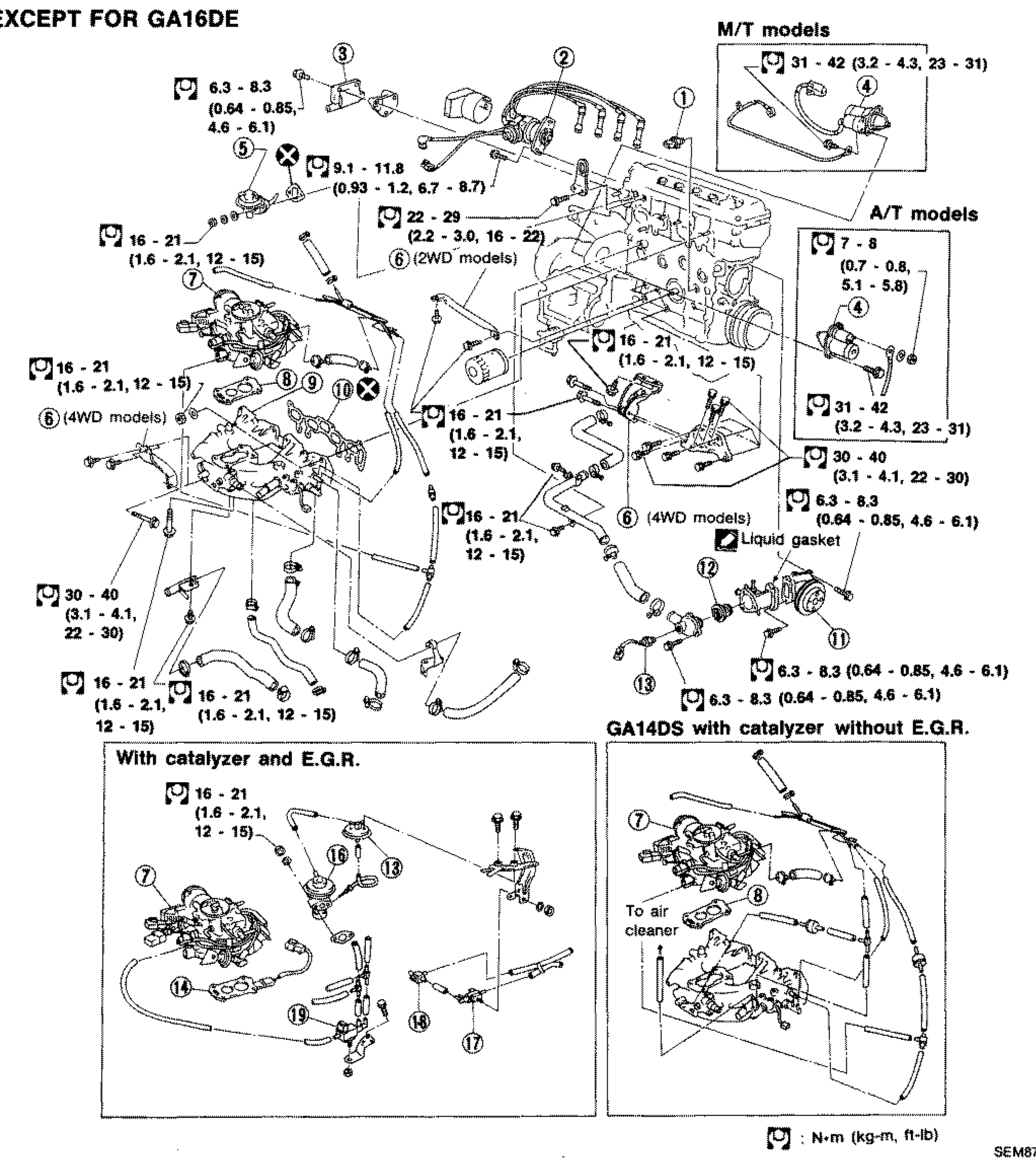
Outer Component Parts (GA)
EM-13Full-page exploded view of the GA engine outer component parts (EXCEPT FOR GA16DE). Shows the carburetor, intake manifold, distributor, ignition coil, starter motor, fuel pump, water pump, thermostat and related hardware with numbered callouts 1-18 and tightening torque values in N·m (kg-m, ft-lb). Inset diagrams cover M/T models, A/T models, 'With catalyzer and E.G.R.', and 'GA14DS with catalyzer without E.G.R.' variants, plus liquid-gasket and 2WD/4WD notes.
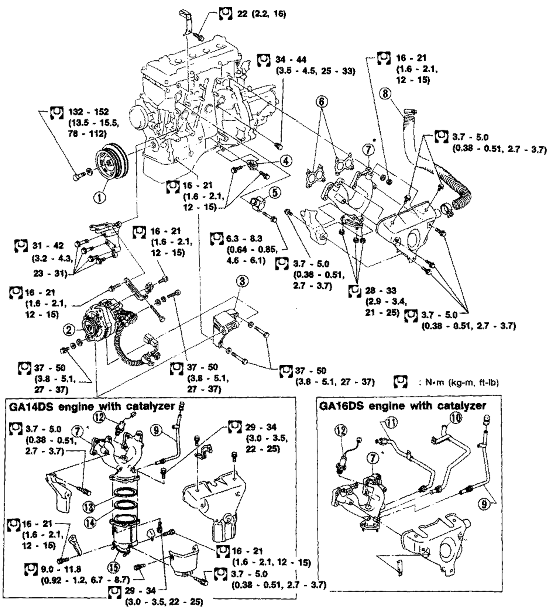
Outer Component Parts (GA) (Cont'd)
EM-14Full-page exploded view of the GA engine outer component parts (EXCEPT FOR GA16DE), front/exhaust side. Shows the crankshaft pulley, alternator and alternator bracket, gusset, water outlet, exhaust manifold and gasket, hot air duct, E.A.I. pipe and related hardware with numbered callouts 1-14 and tightening torque values in N·m (kg-m, ft-lb). Insets cover 'GA14DS engine with catalyzer' and 'GA16DS engine with catalyzer'.
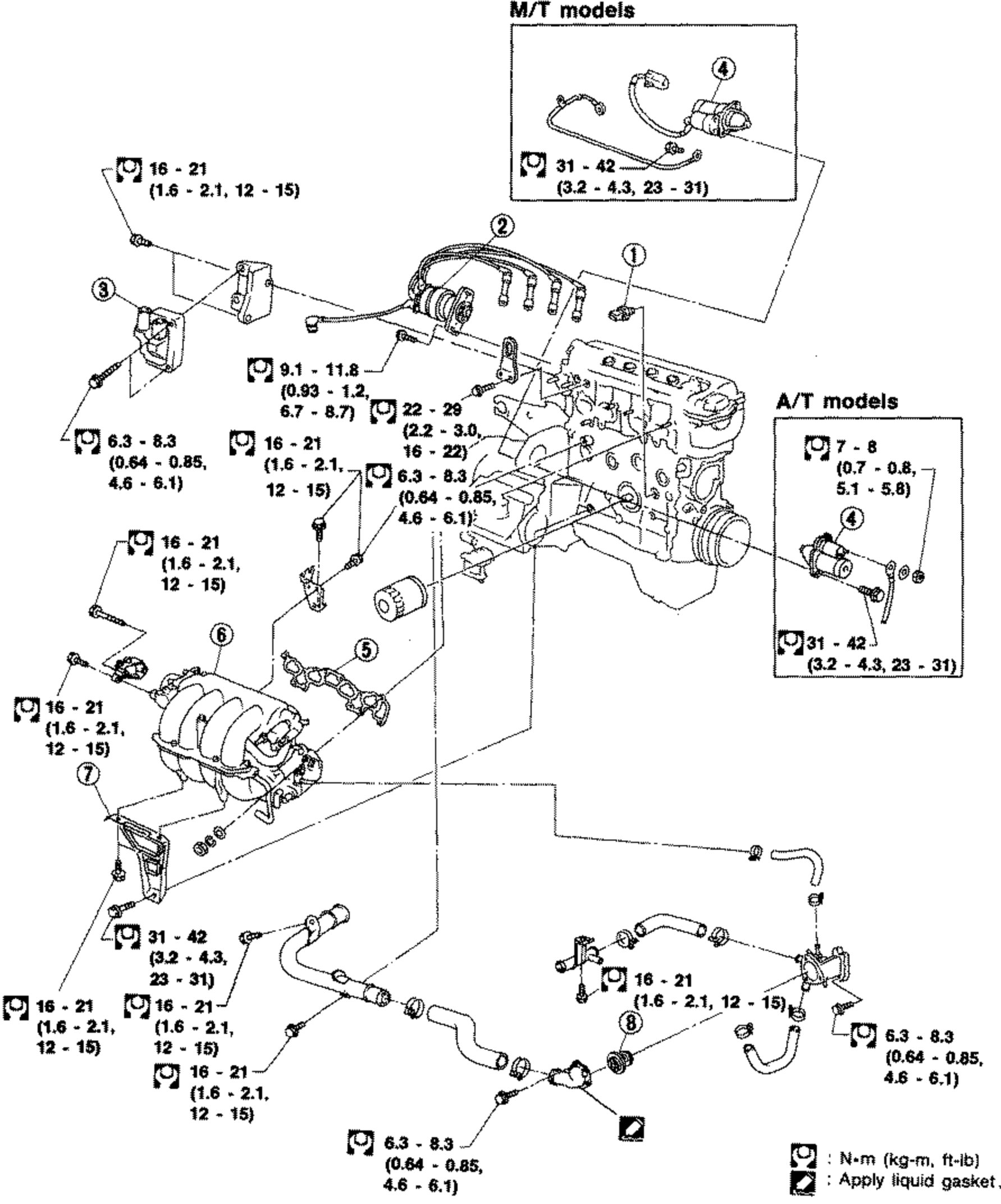
Outer Component Parts (GA16DE)
EM-15Exploded view of GA16DE outer engine components with tightening torque callouts in N·m (kg-m, ft-lb). Shows engine block with ignition coil, crank angle sensor/distributor, oil pressure switch, intake manifold assembly with support, oil filter, thermostat, and starter motor. Inset boxes at top right ('M/T models') and right ('A/T models') show alternate starter motor mounting. Numbered callouts 1-8 identify parts. Apply-liquid-gasket symbol noted in legend.
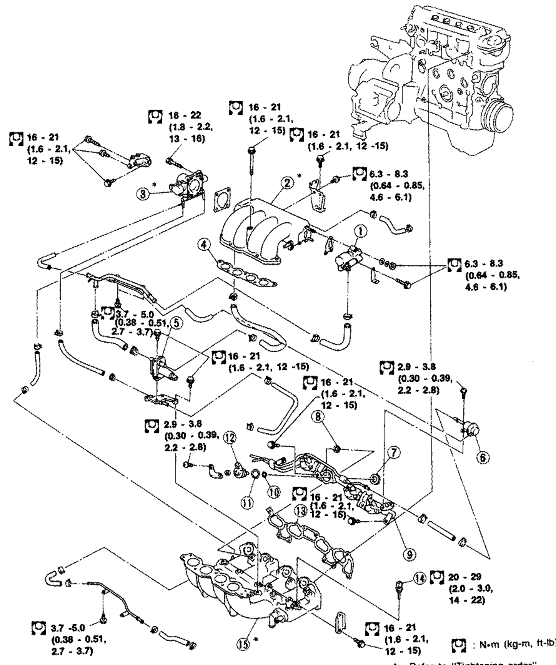
Outer Component Parts (GA16DE) - Intake Manifold
EM-16Exploded view of GA16DE intake manifold and fuel system components with tightening torque callouts in N·m (kg-m, ft-lb). Engine block shown top right. Components include idle air adjusting unit, intake manifold collector, throttle chamber, collector gasket, air regulator, fuel pressure regulator, insulators, fuel gallery assembly with injectors, O-rings, intake manifold gasket, engine temperature sensor, and intake manifold. Numbered callouts 1-15. Note: 'Refer to Tightening order.'
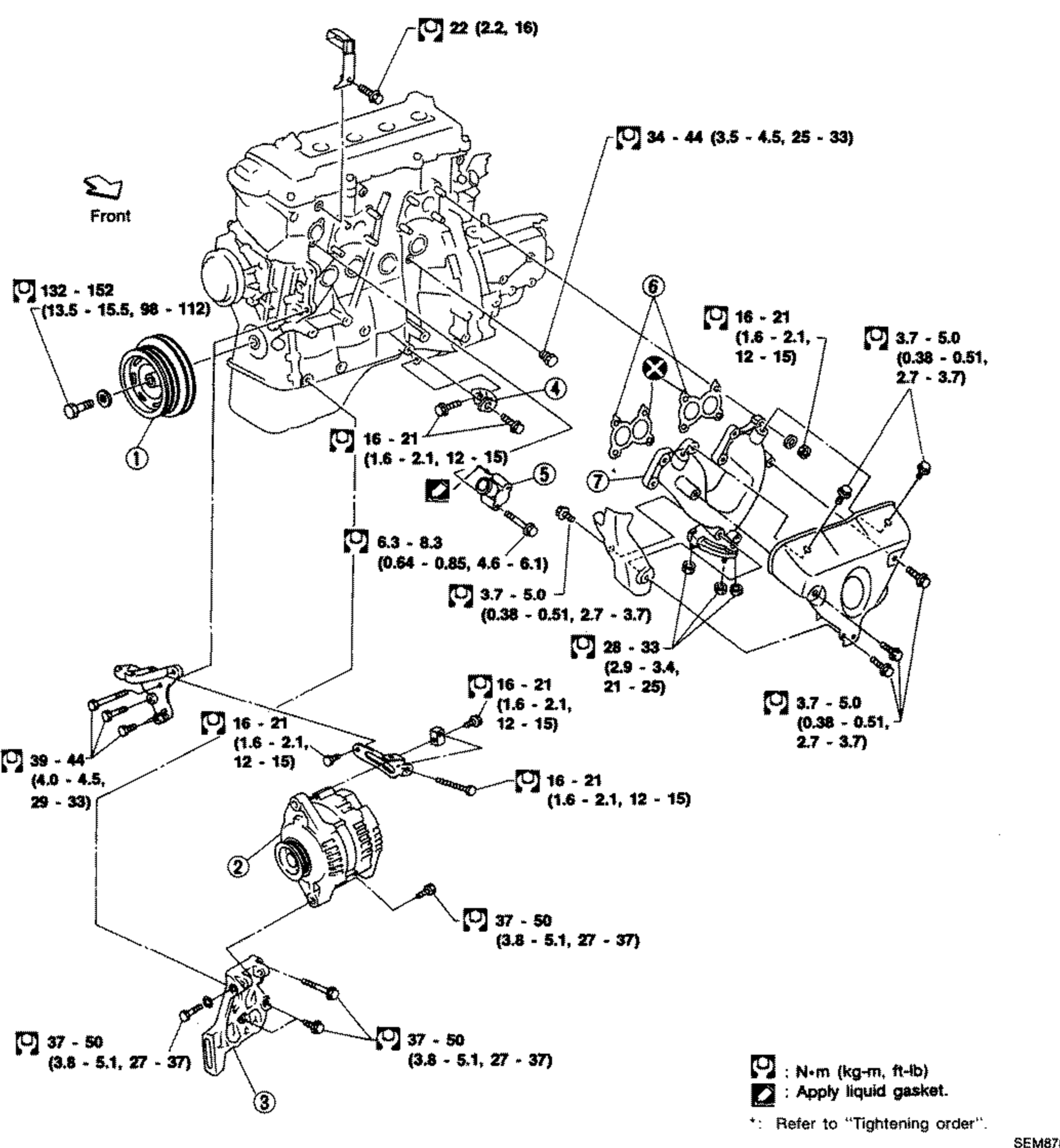
Outer Component Parts (GA16DE) - Exhaust Manifold & Accessory Drive
EM-17Exploded view of GA16DE exhaust manifold and accessory-drive components with tightening torque callouts in N·m (kg-m, ft-lb). Engine block shown with 'Front' arrow at upper left. Components include crankshaft pulley, alternator, compressor bracket, gusset, water outlet, exhaust manifold gasket, and exhaust manifold. Numbered callouts 1-7. Legend notes apply-liquid-gasket symbol and 'Refer to Tightening order'.
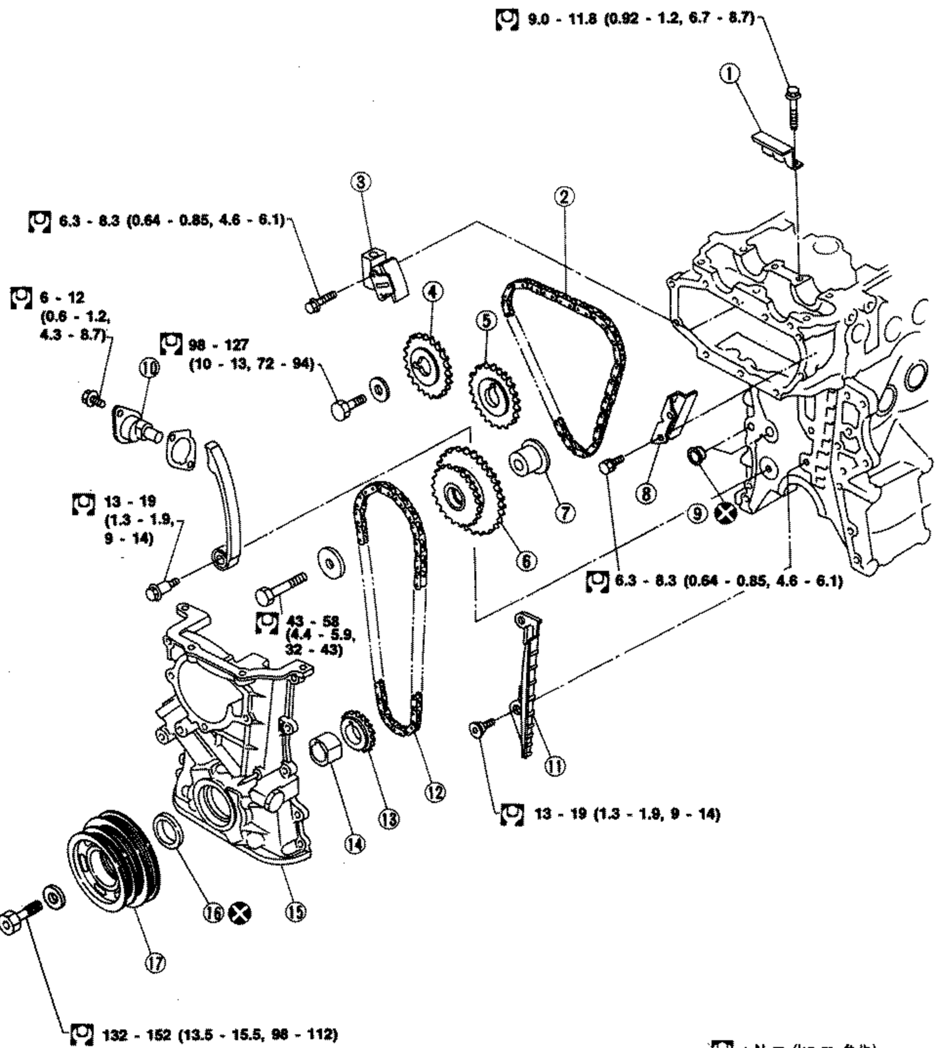
Timing Chain (Except for GA16DE)
EM-22Exploded view of timing chain assembly for engines except GA16DE, with tightening torque callouts in N·m (kg-m, ft-lb). Engine block shown at right. Components include chain guides, upper and lower timing chains, chain tensioners, camshaft sprockets (intake and exhaust), idler sprocket and shaft, O-ring, crankshaft sprocket, oil pump drive spacer, front cover, oil seal, and crankshaft pulley. Numbered callouts 1-17.
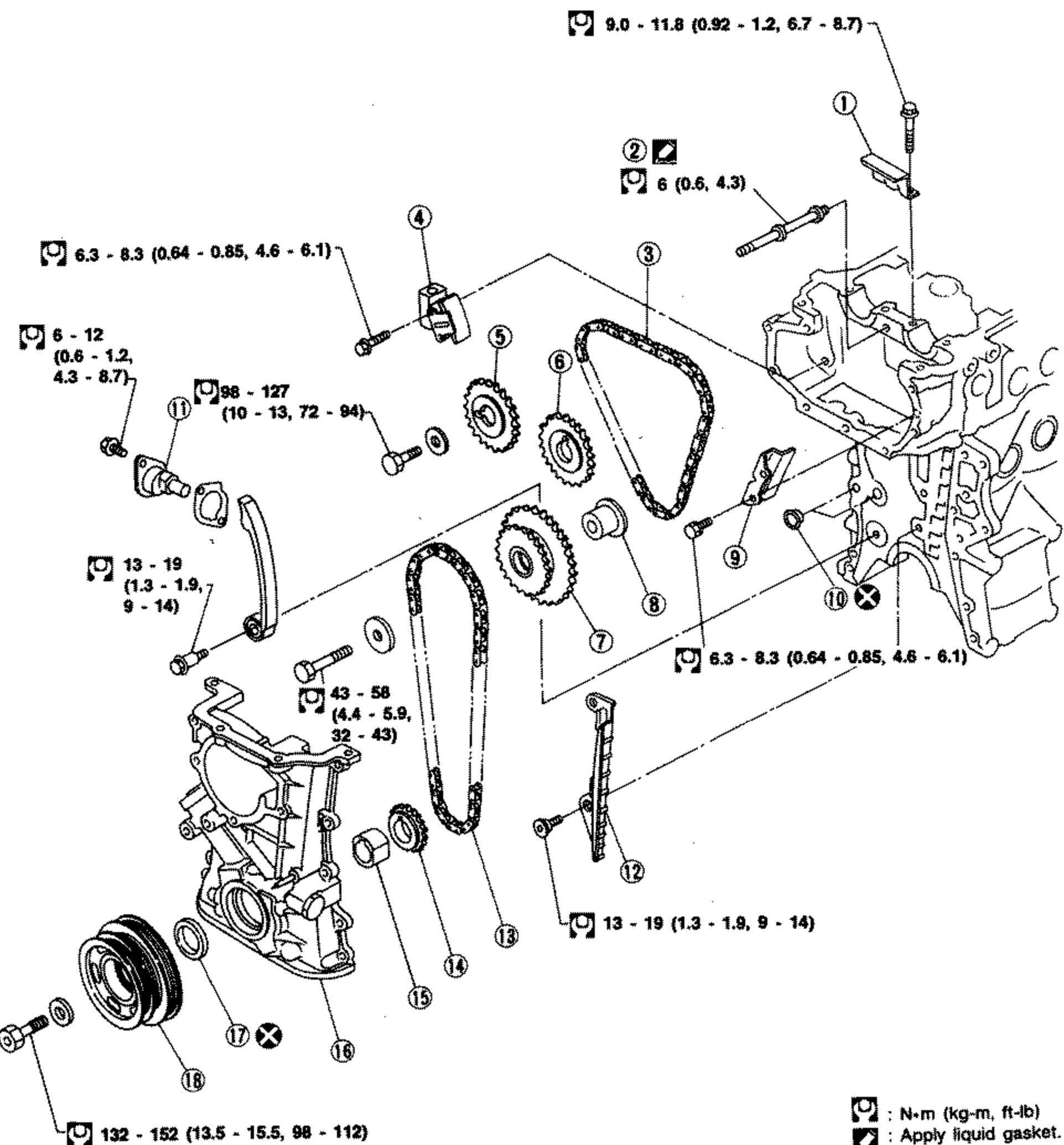
Timing Chain (GA16DE)
EM-23Exploded view of GA16DE timing chain assembly with tightening torque callouts in N·m (kg-m, ft-lb). Engine block shown at right. Components include chain guides, cylinder head front cover gusset, upper and lower timing chains, chain tensioners, camshaft sprockets (intake and exhaust), idler sprocket and shaft, O-ring, crankshaft sprocket, oil pump drive spacer, front cover, oil seal, and crankshaft pulley. Numbered callouts 1-18. Legend notes apply-liquid-gasket symbol.

CYLINDER HEAD
EM-37Full-page exploded view of the GA-series cylinder head assembly (Except for GA16DE). Shows rocker cover, gaskets, intake and exhaust camshafts, camshaft brackets, distributor bracket, valve train (lifters, shims, cotters, springs, seals, retainers, seats), cylinder head, head gasket, front cover gasket and cam sprocket cover. Numbered callouts 1-26 identify each part. Tightening torque callouts (in N·m, kg-m, ft-lb) are placed at the relevant fasteners, and 'Apply liquid gasket' symbols mark sealed joints.

CYLINDER HEAD
EM-38Full-page exploded view of the GA16DE cylinder head assembly. Shows oil filler cap, rocker cover and gasket, oil seal, chain guide, camshaft brackets, intake and exhaust camshafts, distributor bracket, cylinder head bolts, washers, shims, valve lifters, valve cotters, spring retainers, springs, valve oil seals, spring seats, valves, cylinder head, head gasket, cam sprocket cover gusset and cover. Numbered callouts 1-24 identify each part. Tightening torque callouts (N·m, kg-m, ft-lb) and 'Apply liquid gasket' symbols are placed at the relevant joints.

Engine Removal - 2WD Models
EM-49Exploded view of the engine mounting system for 2WD models. Shows numbered components 1-7 (engine front mounting, brackets, rear mounting, center member, buffer, roll damper) with tightening torque callouts in N·m (kg-m, ft-lb) at each bolt location. Includes separate detail insets for M/T models (lower-left and right). Front of vehicle is toward the top.

Engine Removal - 4WD Models
EM-50Exploded view of the engine mounting system for 4WD models. Shows numbered components 1-9 (rear/front engine slingers and mountings, brackets, buffers, front member) with tightening torque callouts in N·m (kg-m, ft-lb) at each bolt location. The engine block is shown centrally with mountings arranged around it.

Cylinder Block
EM-54Exploded view of the cylinder block assembly. Shows numbered components 1-18 including flywheel, rear plate, rear oil seal and retainer, piston rings, snap ring, piston pin, piston, connecting rod and bearings, crankshaft, main/thrust bearings, key, oil pan, drive plate and dust cover. Tightening torque callouts in N·m (kg-m, ft-lb) at fasteners. An A/T models inset (upper right) shows the drive plate and ring gear instead of flywheel. Symbols indicate 'Apply liquid gasket.' Note 'Refer to installation of connecting rod cap.'
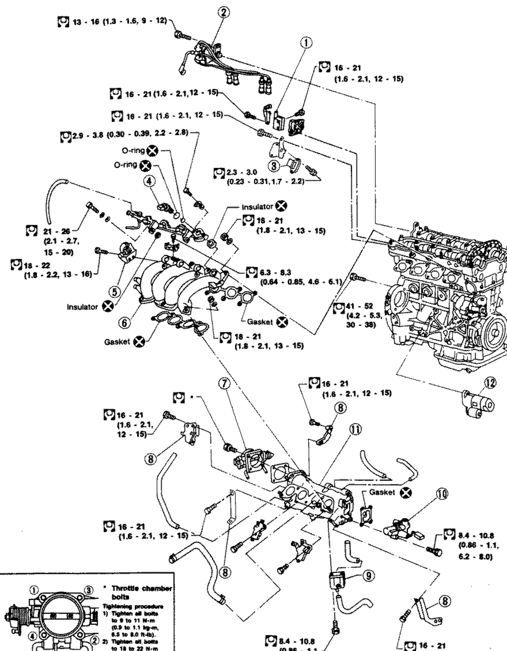
OUTER COMPONENT PARTS - SR20DE
EM-66SR20DE outer component parts exploded view. Shows the engine with intake manifold collector, intake manifold, throttle chamber, ignition coil, distributor, power transistor, injectors, A.A.C. valve, air regulator, and starter motor exploded away from the engine block. Numerous tightening torque callouts (boxed wrench symbols) are spread across the diagram. O-ring and Gasket replacement-part symbols are marked at several joints. Numbered callouts 1-12 identify components.
OUTER COMPONENT PARTS (Cont'd)
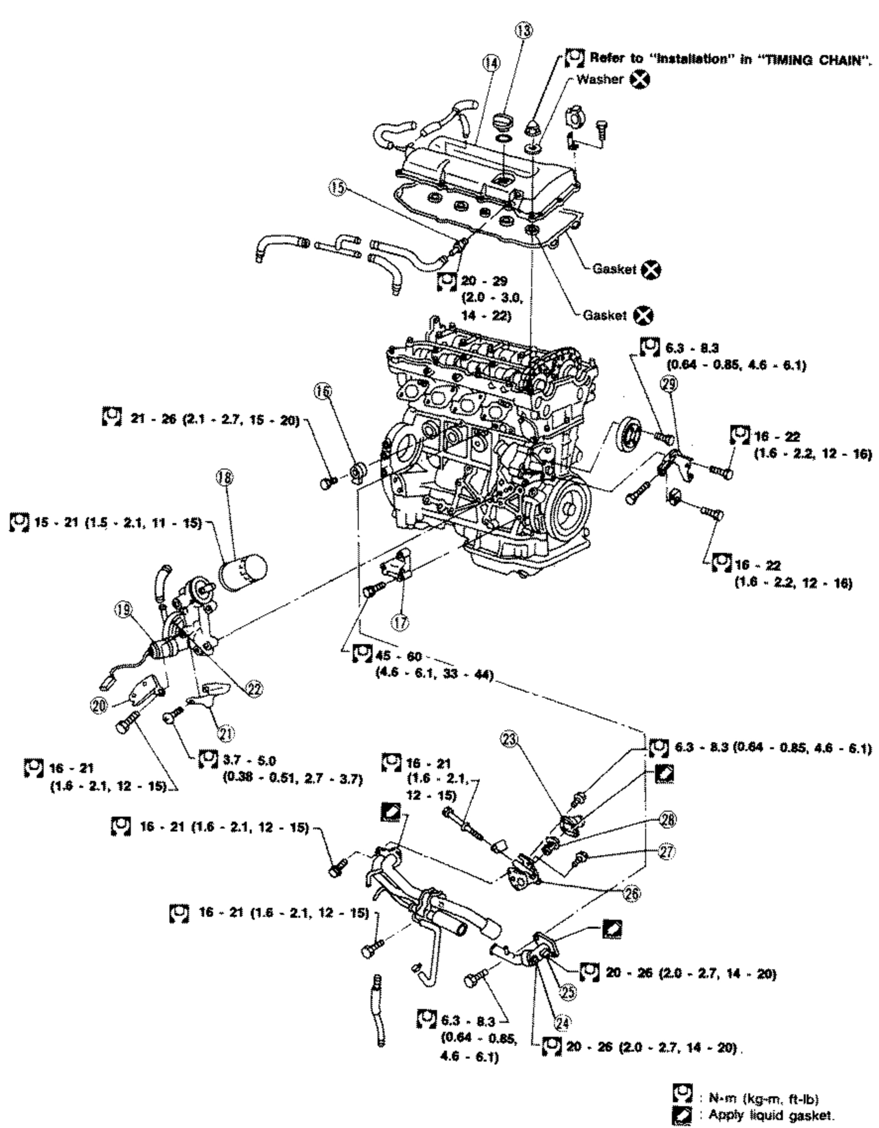
EM-67SR20DE outer component parts exploded view (continued). Shows the engine block with rocker cover, oil filter, oil filter cap, P.C.V. valve, detonation sensor, power steering oil pump bracket, oil pressure switch, intake manifold support, oil catcher, oil cooler, water inlet, thermal transmitter, engine temperature sensor, thermostat housing, air relief plug, thermostat, and power steering oil pump adjusting bar exploded away. Numerous tightening torque callouts in boxed wrench symbols. Gasket and Washer replacement symbols marked at joints. Numbered callouts 13-29 identify components.
OUTER COMPONENT PARTS - SR20DE
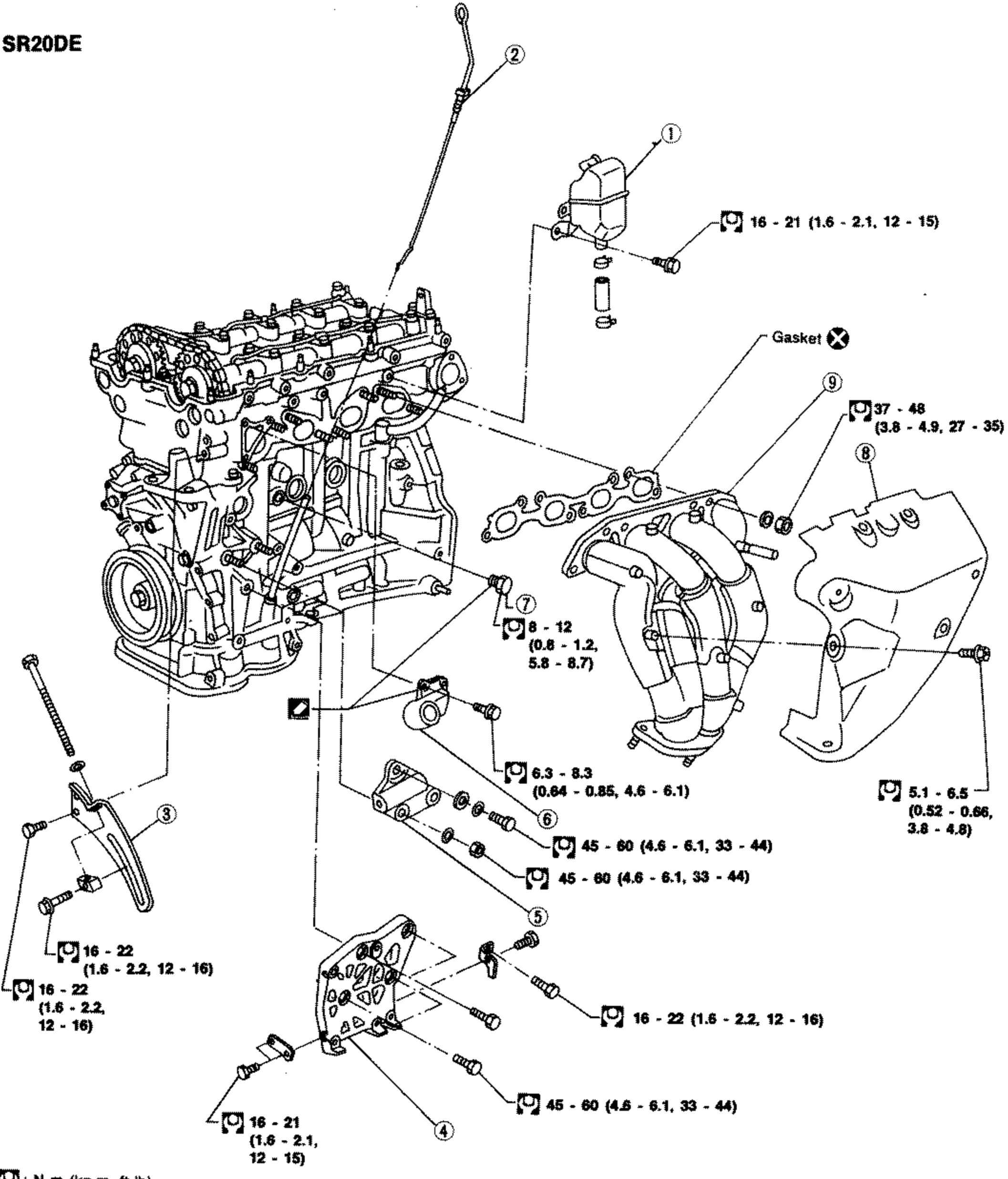
EM-68SR20DE outer component parts exploded view. Shows the engine block with oil separator, oil level gauge, alternator adjusting bar, compressor bracket, alternator bracket, water outlet, drain plug, exhaust manifold cover, and exhaust manifold exploded away. Numerous tightening torque callouts in boxed wrench symbols. A Gasket replacement symbol is marked at the exhaust manifold joint. Numbered callouts 1-9 identify components.
OUTER COMPONENT PARTS - SR20DET
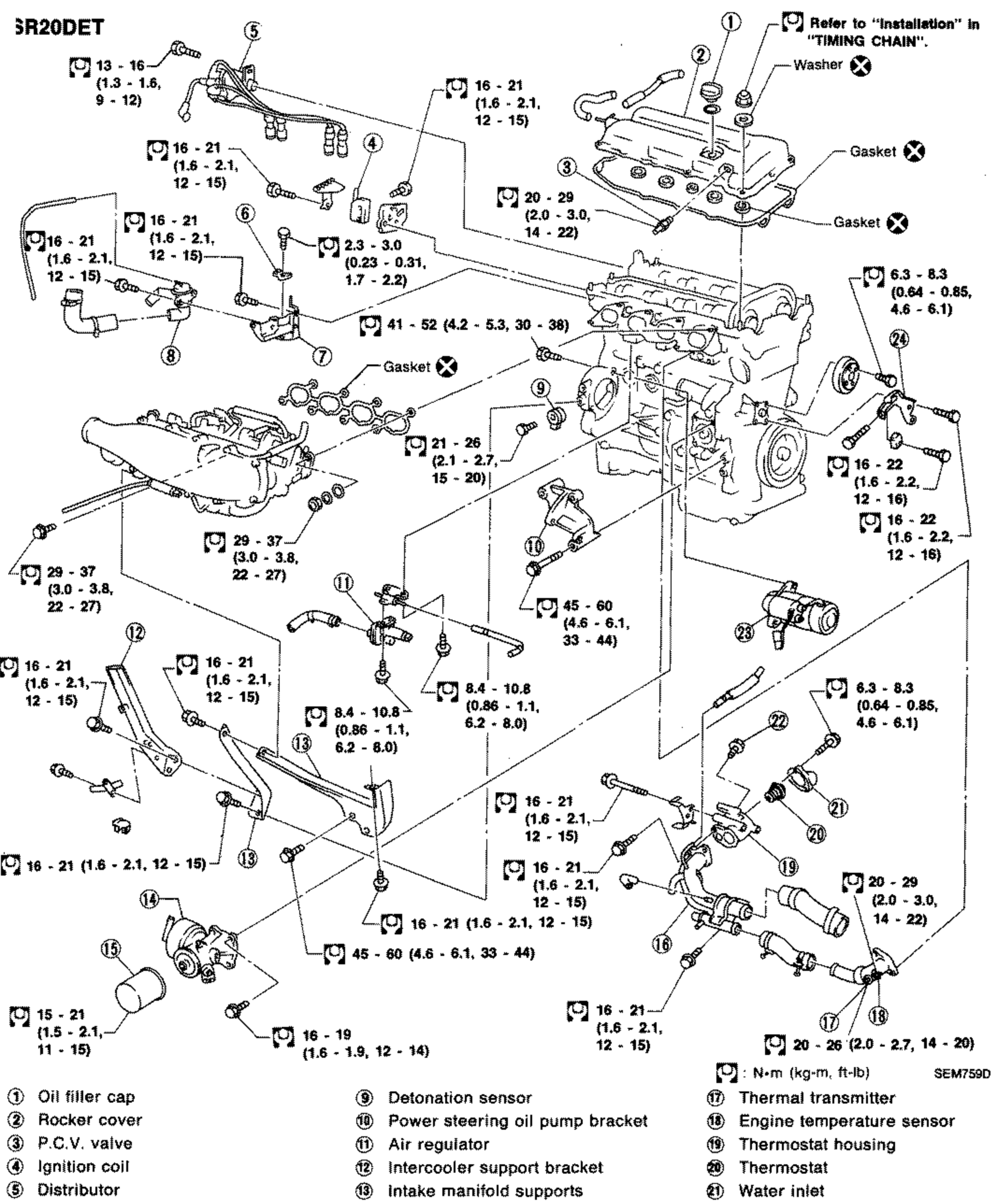
EM-69SR20DET outer component parts exploded view. Shows the engine with oil filler cap, rocker cover, P.C.V. valve, ignition coil, distributor, power transistor, recirculation valve bracket, recirculation valve, detonation sensor, power steering oil pump bracket, air regulator, intercooler support bracket, intake manifold supports, oil cooler, oil filter, water pipe, thermal transmitter, engine temperature sensor, thermostat housing, thermostat, water inlet, air relief plug, starter motor, and power steering oil pump adjusting bar exploded away. Numerous tightening torque callouts in boxed wrench symbols. Gasket and Washer replacement symbols marked at joints. Numbered callouts 1-24.
OUTER COMPONENT PARTS - SR20DET
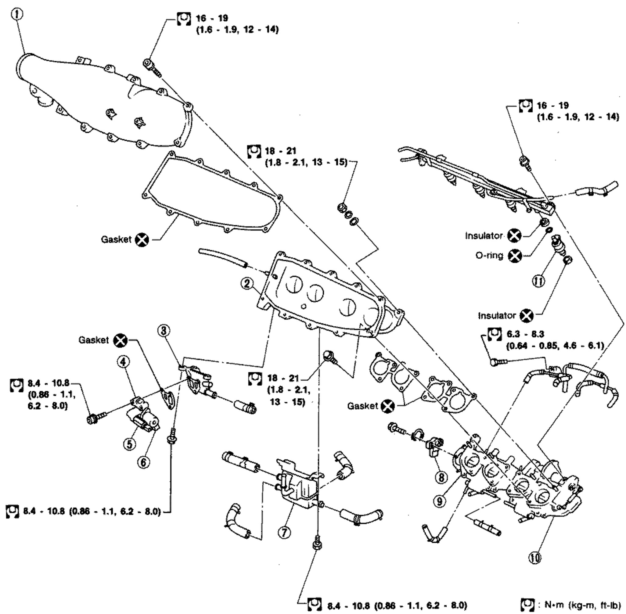
EM-70SR20DET outer component parts exploded view (induction/throttle group). Shows the intake manifold collector, intake manifold, I.A.A. unit bracket, I.A.A. unit, F.I.C.D. solenoid valve, A.A.C. valve, air chamber, throttle sensor, rear throttle chamber, front throttle chamber, and injector exploded away. Numerous tightening torque callouts in boxed wrench symbols. Gasket, Insulator and O-ring replacement symbols marked at joints. Numbered callouts 1-11.
OUTER COMPONENT PARTS - SR20DET
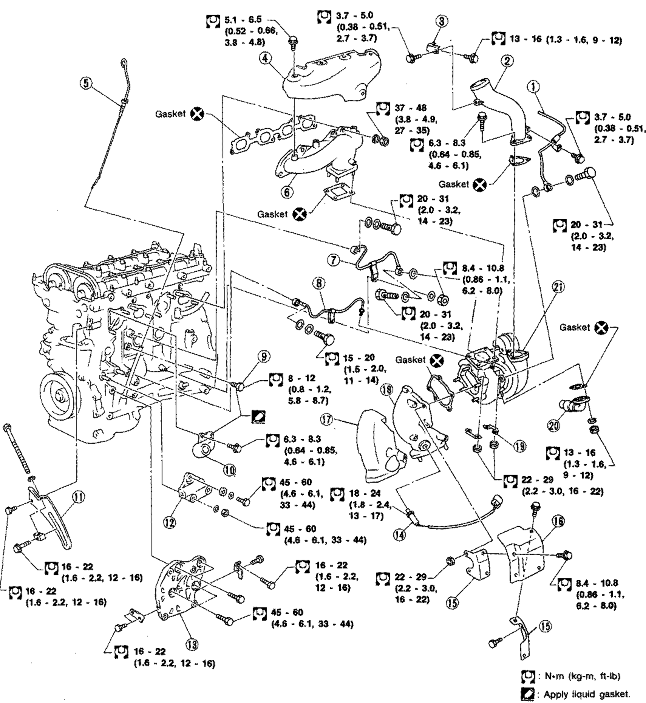
EM-71SR20DET outer component parts exploded view (exhaust/turbocharger group). Shows the engine block with water return tube, air inlet tube, air inlet tube bracket, exhaust manifold cover, oil level gauge, exhaust manifold, water inlet tube, oil inlet tube, drain plug, water outlet, alternator adjusting bar, alternator bracket, compressor bracket, exhaust gas sensor, heat insulator brackets, heat insulator, exhaust outlet cover, exhaust outlet, lock plate, oil return tube, and turbocharger exploded away. Numerous tightening torque callouts in boxed wrench symbols. Gasket replacement symbols marked at joints. Numbered callouts 1-21.
Outer Component Parts - SR20DET
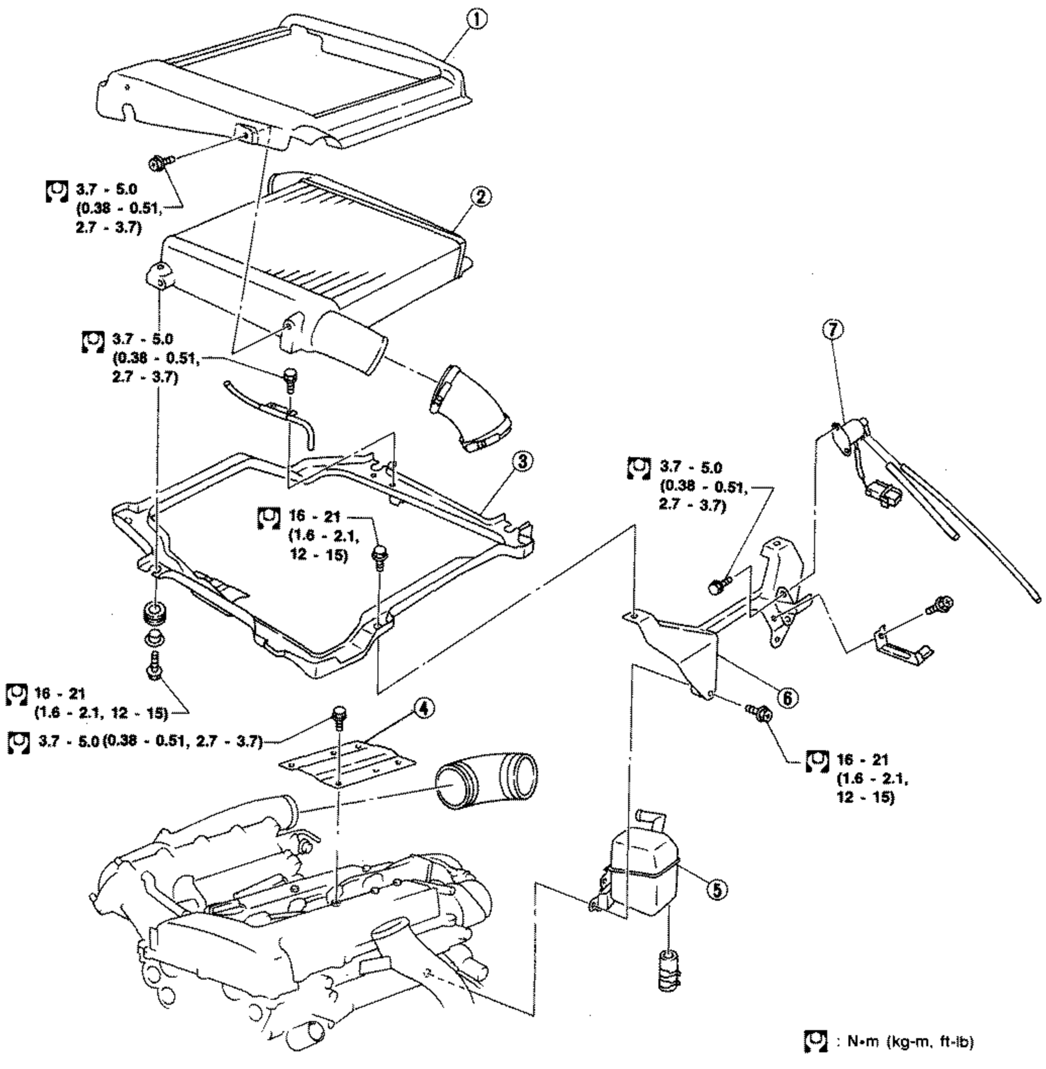
EM-72Exploded view of the SR20DET outer (intercooler) component parts mounted on top of the engine. Numbered callouts 1-7 identify the intercooler cover (1), intercooler (2), intercooler support (3), rocker cover ornament (4), oil separator (5), intercooler support bracket (6), and recirculation valve control solenoid valve (7). Tightening torque values in N·m (kg-m, ft-lb) are shown beside each fastener with bolt-icon markers.
OIL PAN
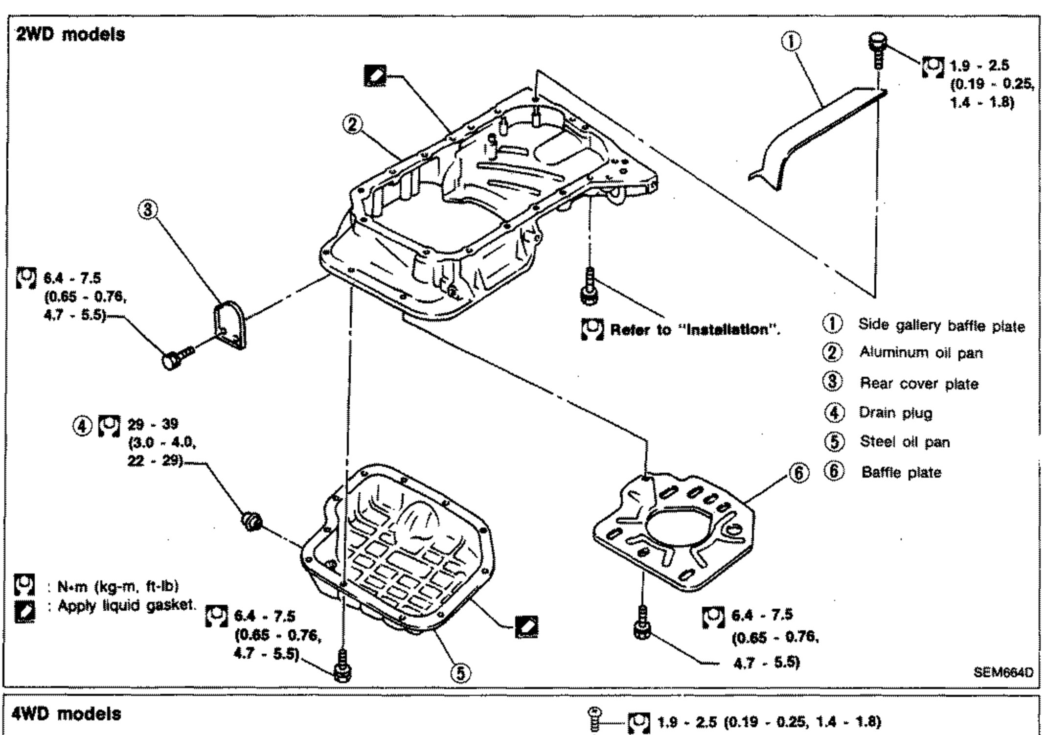
EM-74Oil pan exploded view for 2WD models. Shows side gallery baffle plate, aluminum oil pan, rear cover plate, drain plug, steel oil pan, and baffle plate exploded apart. Tightening torque callouts in boxed wrench symbols. Liquid-gasket symbols at sealing surfaces. Numbered callouts 1-6.
OIL PAN
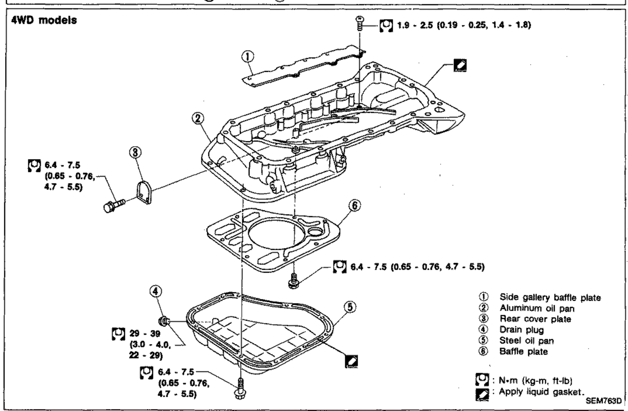
EM-74Oil pan exploded view for 4WD models. Shows side gallery baffle plate, aluminum oil pan, rear cover plate, drain plug, steel oil pan, and baffle plate exploded apart. Tightening torque callouts in boxed wrench symbols. Liquid-gasket symbols at sealing surfaces. Numbered callouts 1-6.

TIMING CHAIN
EM-81Exploded view of the SR-engine timing chain assembly showing cylinder block with R.H. and L.H. camshaft sprockets at top, timing chain, chain guides and chain tensioner, oil pump spacer, front cover, crankshaft sprocket, and crank pulley. Numbered callouts 1-12 identify parts; torque values are given at multiple fastener locations in N·m (kg-m, ft-lb).

CYLINDER HEAD
EM-110Exploded view of the SR20 cylinder head assembly. Shows rocker cover, cylinder head, camshaft, valves, valve springs, rocker arms, chain tensioner, camshaft sprocket and bracket. Numbered callouts 1-24 identify components. Separate insets show 'Turbo models' valve train (intake and exhaust side, outer/inner springs). Torque values: cylinder head bolts area 25-34 N·m (2.5-3.5, 18-25), 12-16 N·m (1.2-1.6, 9-11), 137-157 N·m (14-16, 101-116). Notes reference 'Installation in TIMING CHAIN', washer, rocker cover gasket, O-ring, gasket, and apply liquid gasket symbols.
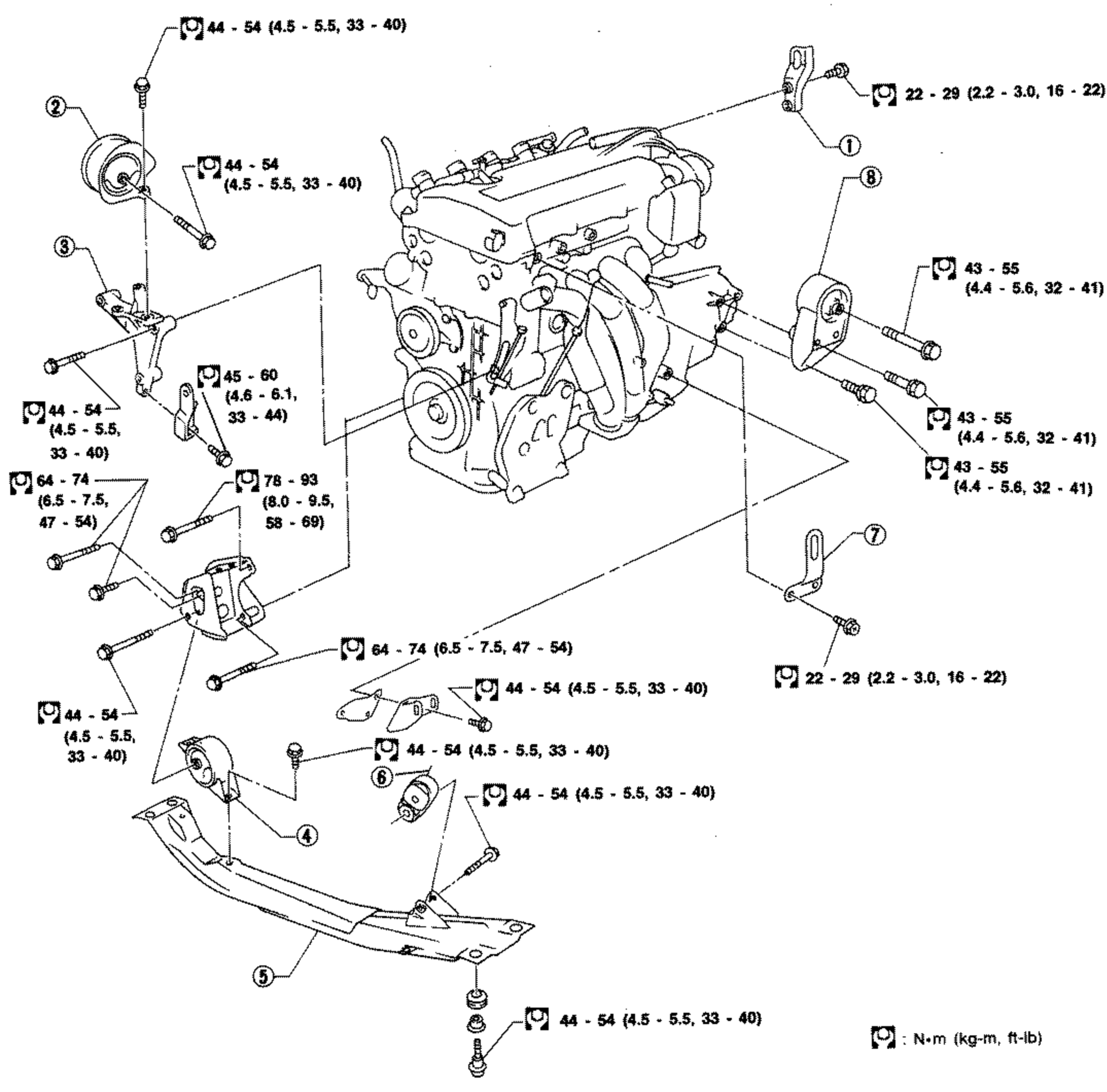
Engine Removal - 2WD models (engine mounting exploded view)
EM-136Exploded view of the 2WD-model engine mounting system showing the engine with numbered mounting components 1-8 and tightening torque callouts for each fastener in N·m (kg-m, ft-lb). Legend identifies the eight numbered parts.
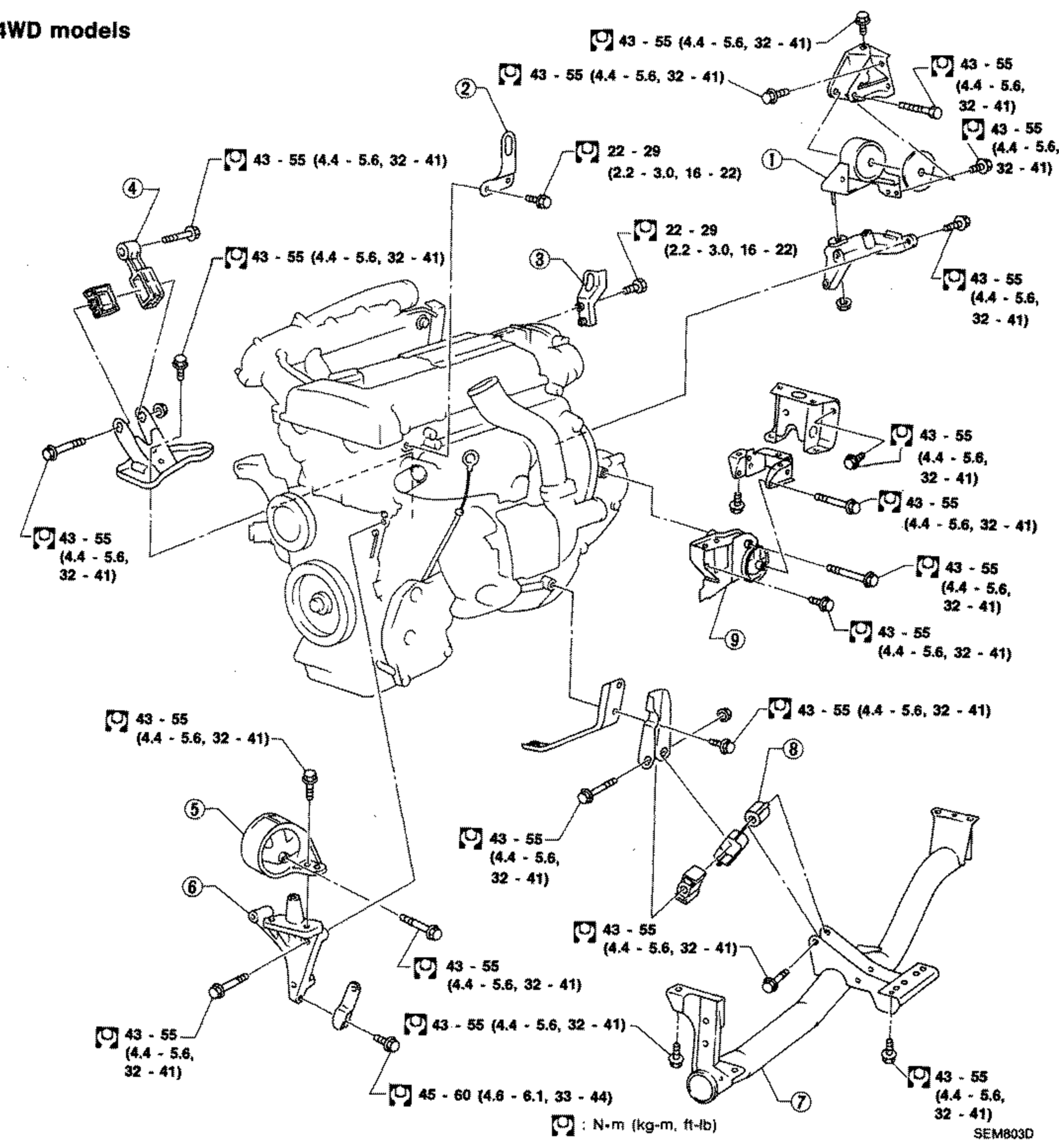
Engine Removal - 4WD models (engine mounting exploded view)
EM-137Exploded view of the 4WD-model engine mounting system showing the engine with numbered mounting components 1-9 and tightening torque callouts for each fastener in N·m (kg-m, ft-lb). Legend identifies the nine numbered parts.
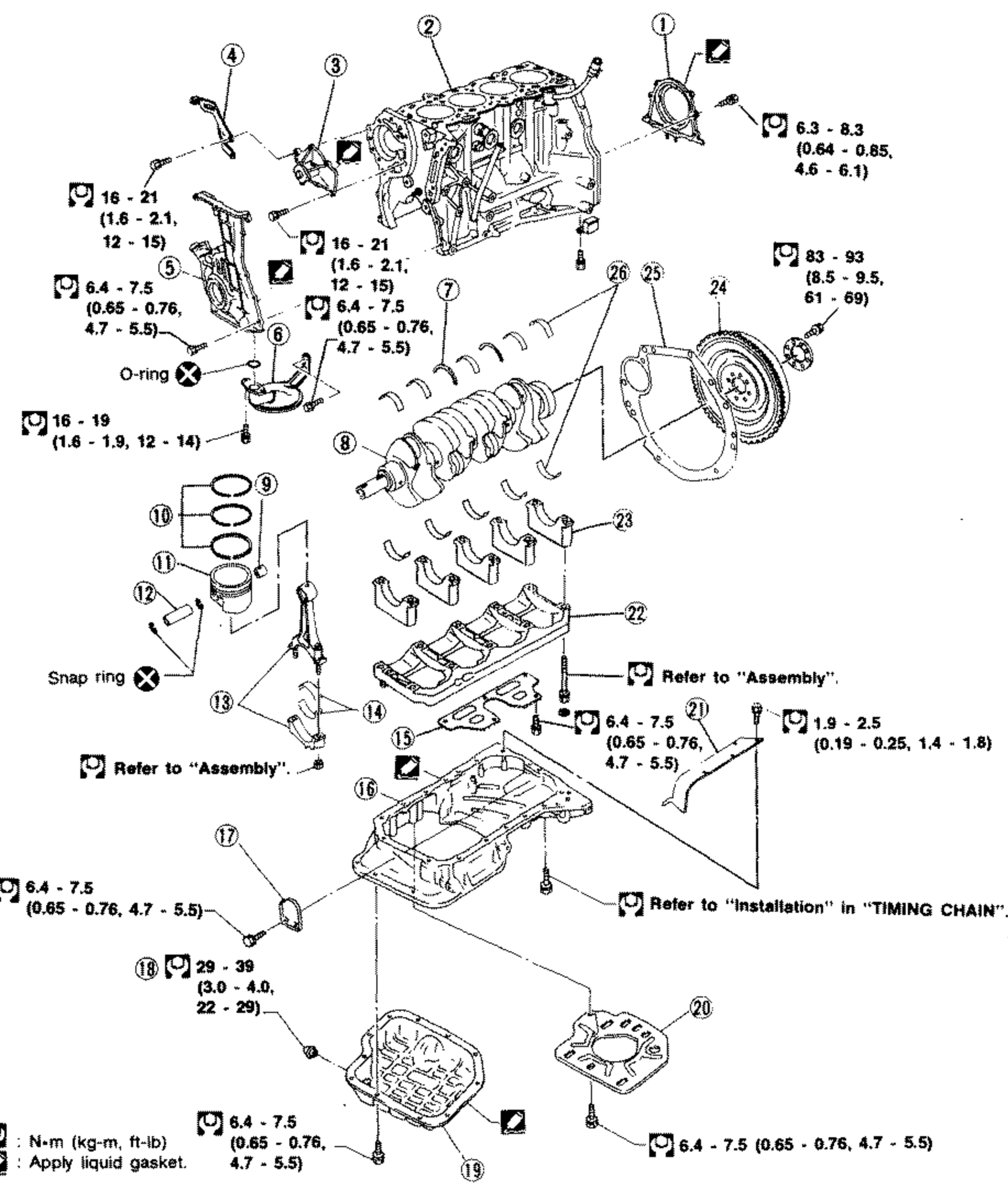
Cylinder Block - SR20DE (exploded view)
EM-142Exploded view of the SR20DE cylinder block assembly with 28 numbered components from rear oil seal retainer through main bearing, including crankshaft, pistons, connecting rods, oil pan and bearings. Numerous tightening-torque callouts in N·m (kg-m, ft-lb) plus 'Refer to Assembly', 'Refer to Installation in TIMING CHAIN', 'Apply liquid gasket', 'O-ring' and 'Snap ring' notes.
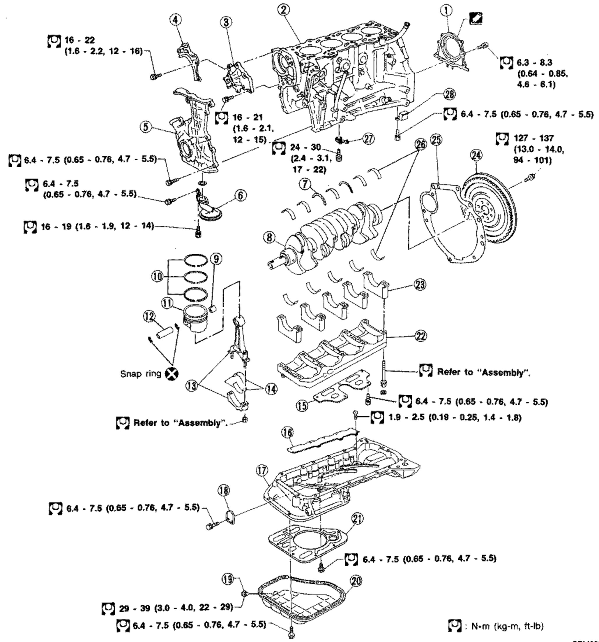
Cylinder Block - SR20DET (exploded view)
EM-143Exploded view of the SR20DET cylinder block assembly with 28 numbered components from rear oil seal retainer through baffle plate, including crankshaft, pistons, connecting rods, oil pan, oil jet and bearings. Numerous tightening-torque callouts in N·m (kg-m, ft-lb) plus 'Refer to Assembly', 'Snap ring' notes.

Outer Component Parts
EM-157Full-page exploded view of engine outer component parts (GA-series engine). Center shows the cylinder block/engine assembly with timing belt cover. Components arranged around it: carburetor/throttle assembly (top), intake manifold, exhaust manifold (top right), distributor (left), oil filter (left), water pump and pulley (right), fuel pump (bottom left), alternator (bottom center), oil pressure switch (bottom left). Numerous tightening torque callouts in N·m (kg-m, ft-lb). A wrench icon legend reads ': N·m (kg-m, ft-lb)'.

Timing Belt
EM-161Exploded view of the timing belt assembly. Left: crankshaft pulley and dust cover. Center: timing belt, belt tensioner, jackshaft pulley, crankshaft sprocket. Right: assembled front view of the timing belt routing around camshaft and crankshaft sprockets with tensioner. Torque callouts: dust cover bolts 9 - 12 N·m (0.9 - 1.2 kg-m, 6.5 - 8.7 ft-lb); belt tensioner / crankshaft sprocket 16 - 21 N·m (1.6 - 2.1 kg-m, 12 - 15 ft-lb). Legend: ': N·m (kg-m, ft-lb)'.

Cylinder Head - Exploded View
EM-169Full-page exploded view of the cylinder head assembly. Components labeled include: Rocker cover, Rocker shaft assembly, Bolt stopper, Valve cotter, Spring retainer, Valve spring, Valve stem oil seal, Valve guide, Cylinder head, Valve seat, Camshaft, Camshaft sprocket, Timing belt cover, Front cover. Tightening torque callouts shown for various fasteners in N·m (kg-m, ft-lb). Note at top right: 'Use new gaskets and oil seals.' Several seals/gaskets marked with X (replace).
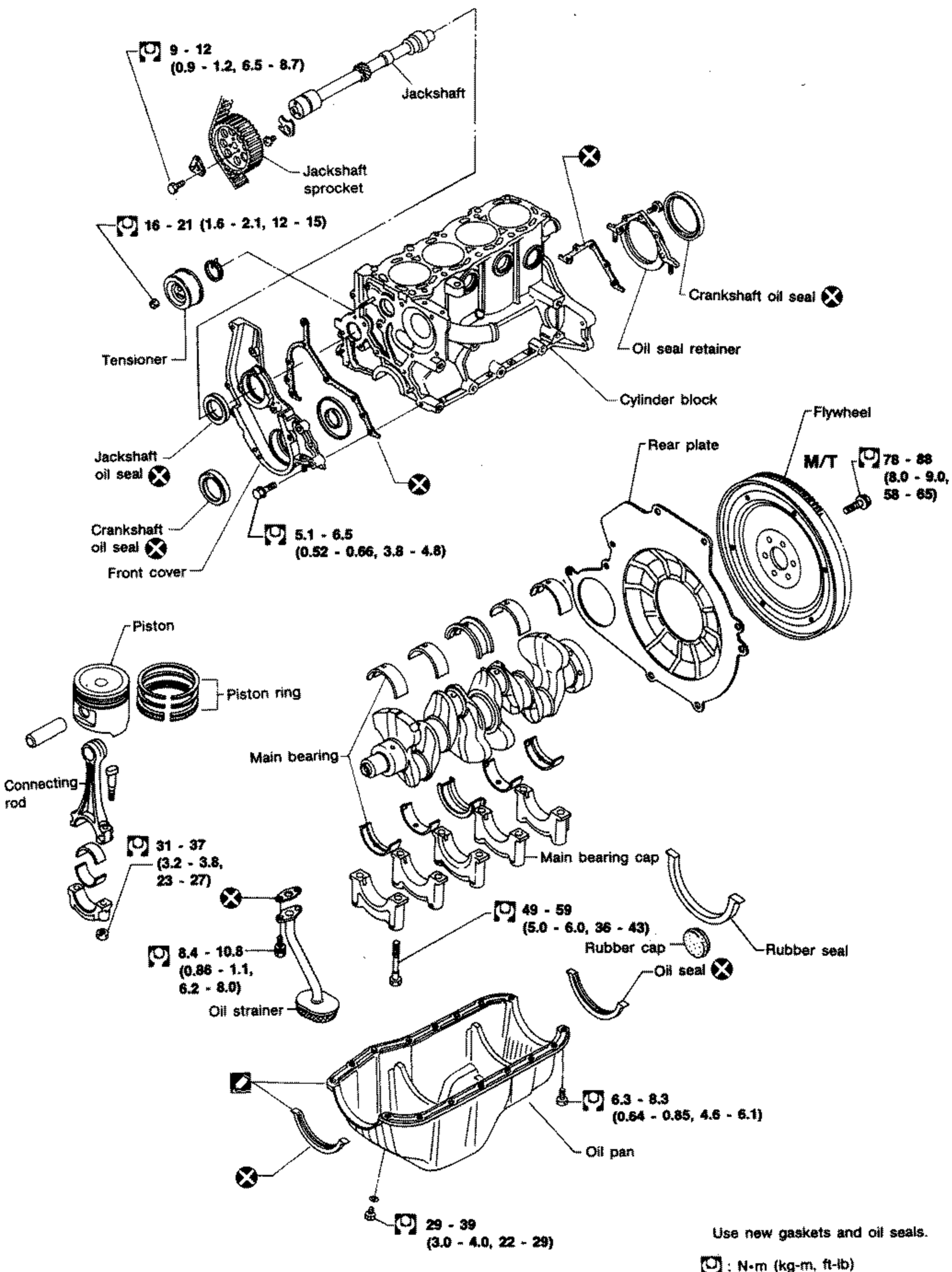
CYLINDER BLOCK
EM-185Exploded view of the cylinder block assembly. Shows the jackshaft and jackshaft sprocket (top), tensioner, jackshaft oil seal, front cover, crankshaft oil seal, cylinder block, crankshaft oil seal and oil seal retainer, rear plate, flywheel (M/T), piston with piston ring, connecting rod, main bearing, main bearing cap, rubber cap, rubber seal, oil seal, oil strainer, and oil pan (bottom). Tightening torque callouts in N·m (kg-m, ft-lb) annotate each fastener; X symbols mark seal/gasket renewal points. Note: 'Use new gaskets and oil seals.'

OUTER COMPONENT PARTS
EM-195Exploded view of CD17 engine outer component parts. Upper diagram shows the engine front with intake manifold, exhaust manifold, alternator, alternator/compressor bracket, compressor, dust cover, and engine R.H. side mounting, each with torque-spec callouts in N-m (kg-m, ft-lb). Lower diagram shows the rear engine slinger, spill tube, glow connecting plate, glow plug, injection nozzle, injection pump, pump bracket, dust cover, rear cover, oil filter, oil cooler, water outlet, bottom by-pass hose, thermostat housing, and lower radiator pipe, each with torque-spec callouts. Note 'Set this side front side (Cylinder No. 1 side)' near the alternator.
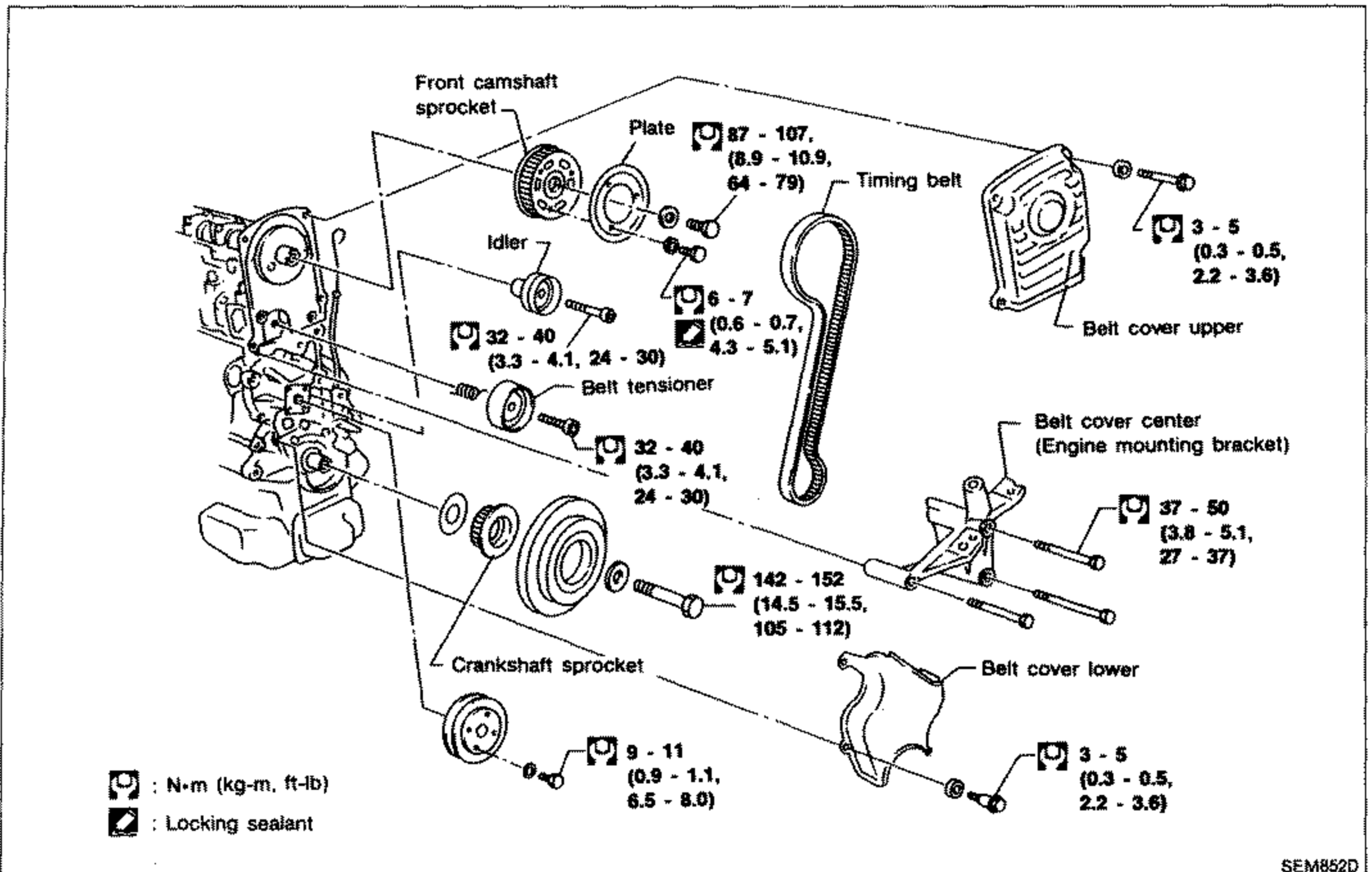
Camshaft Timing Belt — CD20
EM-206Exploded view of the CD20 camshaft timing belt assembly. Shows front camshaft sprocket, plate, idler, belt tensioner, timing belt, crankshaft sprocket, belt cover upper, belt cover center (engine mounting bracket), and belt cover lower. Torque values are given for each fastener in N·m (kg-m, ft-lb). Includes legend: N·m (kg-m, ft-lb) and Locking sealant.

ENGINE REMOVAL
EM-232Full-page exploded view of the engine with its mounting system (engine mounts, brackets, member/crossmember and securing bolts). The engine/transaxle assembly is shown upper-left with belt pulleys. Engine mount insulators and brackets are exploded around it with leader lines to their mounting bolts. Four torque callout boxes all read 44 - 54 N·m (4.5 - 5.5 kg-m, 33 - 40 ft-lb): one at top (upper mount), one at right (mid bracket), one lower-right (rear mount), one lower-left (front mount/member). Footnote at bottom-left gives the wrench-symbol legend 'N·m (kg-m, ft-lb)'.
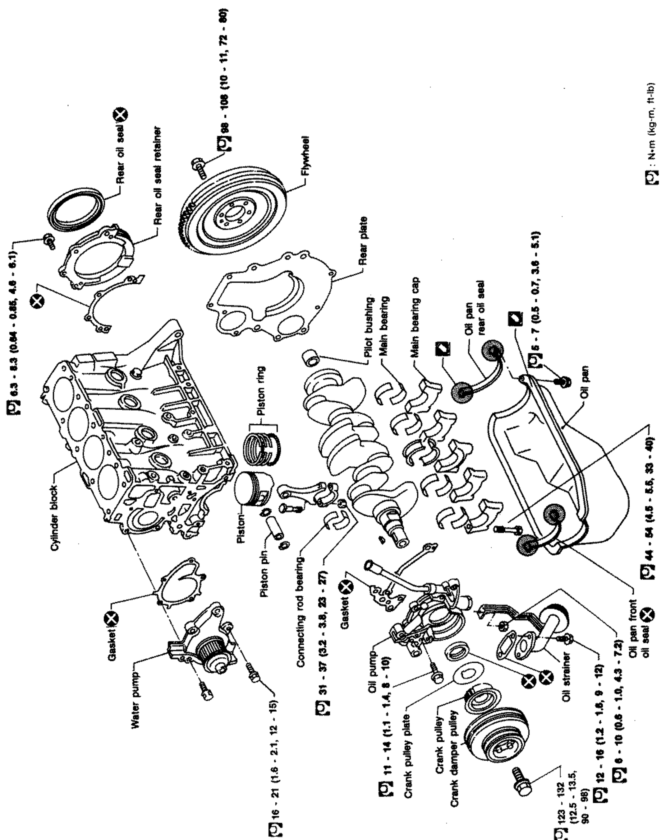
CYLINDER BLOCK
EM-236Full-page exploded view of the CD17 engine cylinder block assembly. Components labelled include: cylinder block, rear oil seal, rear oil seal retainer, flywheel, rear plate, piston ring, pilot bushing, main bearing, main bearing cap, oil pan, rear oil seal, oil pan, gasket, piston, piston pin, connecting rod bearing, oil pump, water pump, oil strainer, crank pulley, crank damper pulley, crank pulley plate, oil pan front oil seal. Tightening torque values in N·m (kg-m, ft-lb) are shown in boxed callouts next to each fastener. Encircled X symbols mark non-reusable parts.
Engine Lubrication & Cooling Systems
LC16 diagrams
Oil Pump
LC-12Exploded view of the oil pump assembly. Shows the front cover (6) with liquid gasket application points, oil pump cover (2) with inner gear (4) and outer gear (5), screws (1), bolts (3), regulator valve (7), spring (8), washer (9) and plug (10). Tightening torque callouts: screw (1) 3.7 - 5.0 N·m (0.38 - 0.51 kg-m, 2.7 - 3.7 ft-lb); bolt (3) 6.3 - 8.3 N·m (0.64 - 0.85 kg-m, 4.6 - 6.1 ft-lb); plug (10) 39.2 - 58.8 N·m (4.00 - 6.00 kg-m, 28.9 - 43.4 ft-lb). Arrows point to 'Front cover side', 'Oil pump cover side' and 'Groove' on the gears.

Water Pump
LC-16Exploded view of the water pump assembly with mounting bolts and the water pump pulley. Liquid gasket application points are called out. Bolt tightening torque callouts of 6.3 - 8.3 N·m (0.64 - 0.85 kg-m, 4.6 - 6.1 ft-lb) shown at multiple locations. Labels: 'Water pump', 'Water pump pulley', 'Liquid gasket'.

Radiator
LC-19Exploded view of the radiator assembly with cooling fan and motor. Numbered callouts 1-13: reservoir tank, reservoir tank bracket, radiator cap, mounting bracket, upper hose, washer, drain plug, mounting rubber, oil cooler hose (A/T models), radiator, lower hose, fan, fan motor. A 'For coupe' detail is shown at top left. Tightening torque callouts of 3.7 - 5.0 N·m (0.38 - 0.51 kg-m, 2.7 - 3.7 ft-lb) shown at several fasteners.

Engine Lubrication System - Oil Pump (Cont'd) - Disassembly and Assembly / Installation
LC-32Exploded view of the oil pump assembly with numbered callouts 1-10 and tightening torque specs (in N·m, kg-m, ft-lb). Shows oil pump cover, front cover, inner gear, outer gear, regulator valve, spring, washer, plug, regulator valve set, oil strainer, O-ring, and liquid gasket application points. Includes a separate inset for 4WD models. Torque values: 3.7-5.0 (0.38-0.51, 2.7-3.7); 6.4-7.5 (0.65-0.76, 4.7-5.5) at two locations; 16-19 (1.6-1.9, 12-14); 39-69 (4.0-7.0, 29-51). 4WD inset: 6.4-7.5 (0.65-0.76, 4.7-5.5) and 16-19 (1.6-1.9, 12-14).
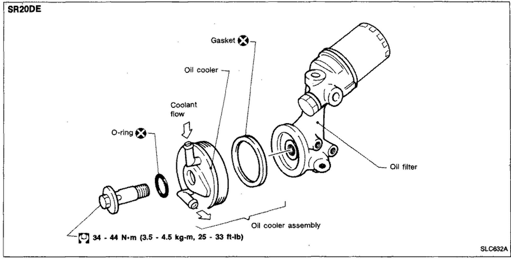
Oil Cooler
LC-35SR20DE oil cooler exploded view showing gasket, oil cooler, O-ring, oil filter, oil cooler assembly and mounting bolt. Arrows indicate coolant flow. Bolt tightening torque callout shown.
Oil Cooler
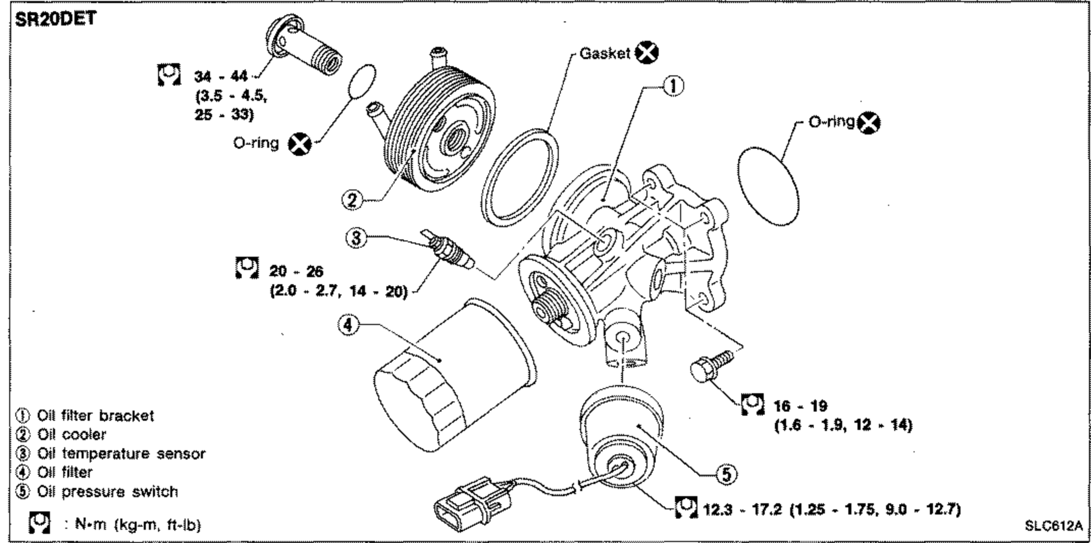
LC-35SR20DET oil cooler exploded view with numbered callouts 1-5: oil filter bracket, oil cooler, oil temperature sensor, oil filter, oil pressure switch. Includes gasket, two O-rings, and multiple torque callouts.
Water Pump (Cont'd) / Thermostat
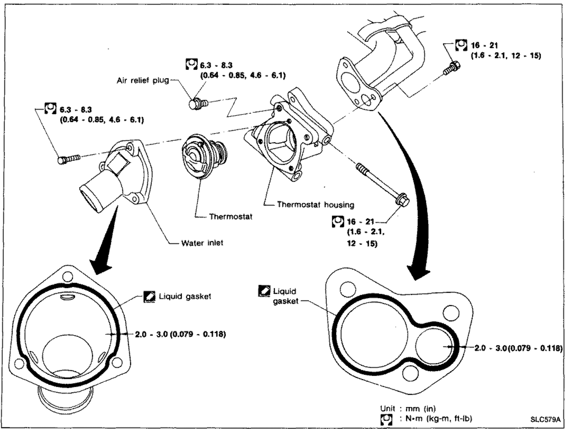
LC-39Thermostat exploded view showing air relief plug, thermostat, thermostat housing, water inlet, and mounting bolts with torque callouts. Two lower inset views show the liquid gasket bead application areas with bead width spec. Unit and torque legend in bottom-right.
Radiator (Aluminum type)
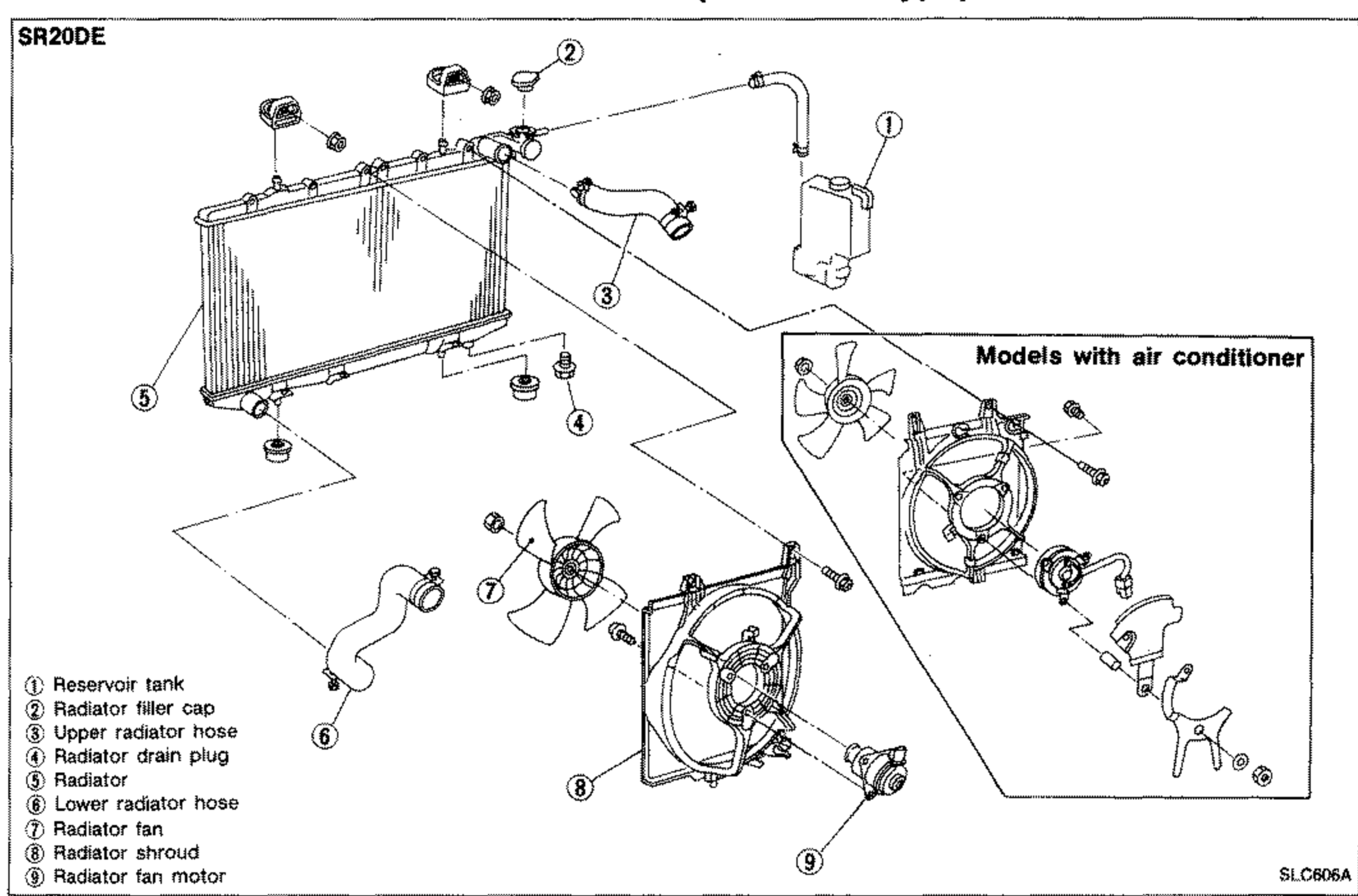
LC-41SR20DE aluminum radiator exploded view with numbered callouts 1-9: reservoir tank, radiator filler cap, upper radiator hose, radiator drain plug, radiator, lower radiator hose, radiator fan, radiator shroud, radiator fan motor. Includes an inset for models with air conditioner.
Radiator (Aluminum type)
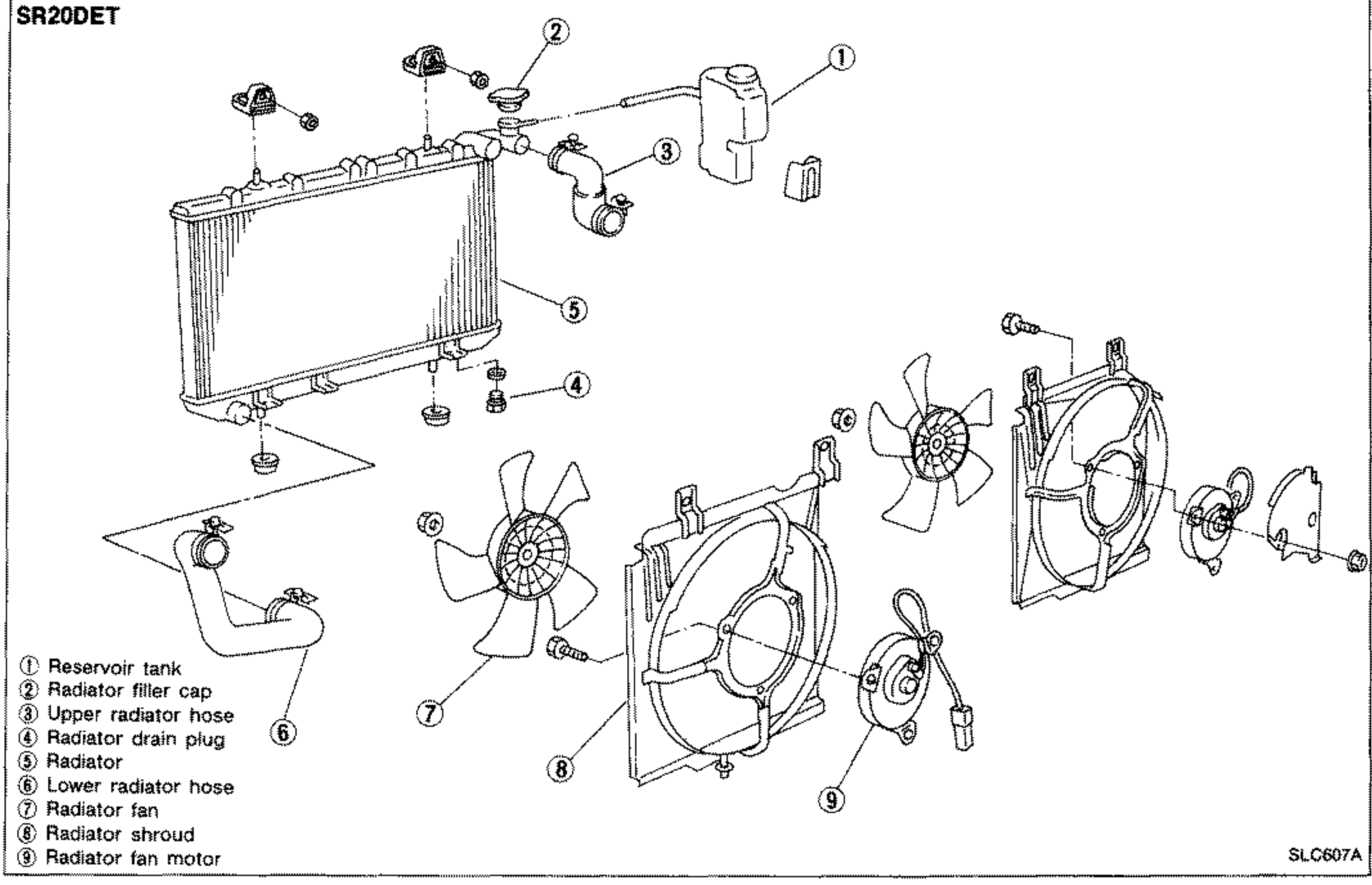
LC-41SR20DET aluminum radiator exploded view with numbered callouts 1-9: reservoir tank, radiator filler cap, upper radiator hose, radiator drain plug, radiator, lower radiator hose, radiator fan, radiator shroud, radiator fan motor.

Oil Pump
LC-44Exploded view of the engine oil pump. The pump body (upper right) houses the inner rotor & drive gear and the outer rotor. To the left, the pump cover separates from the body via a gasket (replacement-required symbol). Cover bolts and a mounting bolt and nut secure the assembly. To the right, the pressure regulator valve, spring, washer and cap thread into the body. Tightening-torque callouts are given in N·m (kg-m, ft-lb). Note: 'If damaged, replace valve set.'

Cooling System Inspection / Water Pump
LC-47Exploded view of the water pump assembly. The pulley (left) bolts on with torque 6.3 - 8.3 N·m (0.64 - 0.85 kg-m, 4.6 - 6.1 ft-lb). The water pump body (right) mounts via a gasket (replacement-required symbol) and water pump bolts torqued to 5.1 - 6.5 N·m (0.52 - 0.66 kg-m, 3.8 - 4.8 ft-lb). Tightening torques given in N·m (kg-m, ft-lb).

Thermostat
LC-48Exploded view of the thermostat and housing. The thermostat housing (upper right) connects 'To heater unit'. The thermostat fits into the water outlet housing (left) with its air vent hole oriented 'Up'. A gasket (replacement-required symbol) seals between housings. Bolts on both sides are torqued to 5.1 - 6.5 N·m (0.52 - 0.66 kg-m, 3.8 - 4.8 ft-lb).

Radiator / Thermoswitch
LC-49Exploded view of the radiator assembly. Shows the radiator core with upper/lower tanks, radiator cap, drain plug, mounting rubbers, the reservoir tank (upper right), upper and lower radiator hoses with clamps, the thermoswitch (lower left), and the cooling fan, motor and fan shroud (right). The thermoswitch torque is 5 - 10 N·m (0.5 - 1.0 kg-m, 3.6 - 7.2 ft-lb).

Engine Lubrication System — Oil Pump (Cont'd) Disassembly and Assembly
LC-55CD17 oil pump exploded view. Components: gasket (with Q symbol), oil pump body, cover, inner gear, outer gear, regulator valve, spring, washer, cap, oil strainer. Torque values: cover bolts 4-5 N·m (0.4-0.5, 2.9-3.6); cap 39-49 N·m (4.0-5.0, 29-36); oil strainer 12-16 N·m (1.2-1.6, 9-12). N·m (kg-m, ft-lb).

Engine Lubrication System — Oil Pump (Cont'd) Disassembly and Assembly
LC-55CD20 oil pump exploded view. Components: oil pump body, cover, inner gear, outer gear, regulator valve, spring, shim, washer. Torque values: cover bolts 3.7-5.0 N·m (0.38-0.51, 2.7-3.7); regulator valve plug 39-69 N·m (4.0-7.0, 29-51). N·m (kg-m, ft-lb).

Engine Lubrication System — Oil Cooler
LC-58Oil cooler exploded view (top to bottom): oil cooler cover, O-ring (Q symbol), oil cooler stud, oil cooler, O-ring (Q symbol), gasket with O-ring (Q symbol), oil cooler support, bolt. Torque values: cover 20-25 N·m (2.0-2.5, 14-18); oil cooler stud 34-44 N·m (3.5-4.5, 25-33); support bolt 16-19 N·m (1.6-1.9, 12-14). N·m (kg-m, ft-lb).
Engine Fuel & Emission Control System
EF & EC7 diagrams
CARBURETOR
EF & EC-150Full-page exploded view of the carburetor assembly with numbered callouts 1–29 identifying every component, plus tightening-torque values in N·m (kg-m, ft-lb) at multiple fasteners. Some parts differ between 'With catalyzer' and 'Without catalyzer' variants, called out on the diagram.

IGNITION CONTROL SYSTEM — Distributor
EF & EC-187Exploded view of the MITSUBISHI-make distributor for GA13DS/GA14DS/GA16DS. Numbered callouts: 1 Cap, 2 Rotor, 3 Rubber ring, 4 Cover, 5 IC ignition unit, 6 Vacuum controller, 7 Housing assembly, 8 O-ring. An inset box at upper right shows the GA14DS models with catalyzer vacuum controller (callout 6).

IGNITION CONTROL SYSTEM — Distributor
EF & EC-188Exploded view of the HITACHI-make distributor for GA13DS/GA14DS/GA16DS. Numbered callouts 1 through 14: 1 Cap, 2 Rotor head, 3 Reluctor, 4 IC ignition unit, 5 Rotor shaft setting screw, 6 Rotor shaft, 7 Governor spring, 8 Governor weight, 9 Shaft assembly, 10 Rubber ring, 11 Vacuum controller, 12 Housing, 13 O-ring, 14 Coupling. An inset box at left shows the CA14DS models with catalyzer vacuum controller (callout 11).

Carburetor - Exploded View
EF & EC-647Full-page exploded view of the carburetor assembly. Top section is the choke chamber with the automatic choke heater bimetal cover, vacuum break diaphragm, diaphragm for secondary system, float, secondary main jet, primary main jet, injection weight, primary slow jet, accelerating pump piston, and primary slow air bleed. Center body shows fuel needle valve, primary/secondary main air bleeds, power jet, secondary small venturi, secondary slow jet/air bleed, primary small venturi, and fuel cut solenoid valve. Bottom is the throttle chamber with throttle lever, lock lever, dash pot and adjusting screws, throttle opener adjusting screw, throttle/idle adjusting screws, limiter cap, and fast idle adjusting screw. Tightening torque callouts shown with wrench symbols.

Carburetor - Structure
EF & EC-648Full-page cutaway cross-section drawing of the carburetor showing internal structure. Labeled callouts (left to right and top to bottom): fuel needle valve, accelerating pump piston, secondary slow jet, secondary slow air bleed, secondary main air bleed, secondary main nozzle, injection nozzle, choke valve, primary main nozzle, primary main air bleed, primary slow air bleed, primary slow jet, vacuum piston, float, inlet check ball, secondary main jet, secondary throttle valve, outlet check ball, primary throttle valve, idle hole, idle adjusting screw, power jet, and primary main jet.

IGNITION CONTROL SYSTEM — Distributor — Construction
EF & EC-659Exploded view of the distributor assembly, drawn vertically. Top-left shows the distributor cap (insulation resistance: More than 50 M-ohm) with carbon point (length more than 10 mm / 0.39 in), rotor head (insulation resistance more than 50 M-ohm), roll pin, reluctor, stator, magnet, IC ignition unit, spacer, breaker plate and vacuum controller down the left column. Right column shows packing, rotor shaft setting screw, rotor shaft, governor spring, governor weight, shaft, housing, harness, O-ring, collar and roll pin. High-temperature grease points are marked with a grease-can symbol next to several joints.

VE-TYPE INJECTION PUMP - Disassembly (With Cold Start Device)
EF & EC-668Exploded view of the VE-type injection pump disassembly with cold start device. Shows the fast idle control lever and its adjusting screw, governor control lever and its adjusting screw, control lever, bracket, springs, O-rings, pump cover, pump housing, governor control shaft, cold start device assembly and its linkage adjusting screw, control wire bracket, roller and roller holder, and distributor head. Several callouts include tightening torque values in N·m (kg-m, ft-lb).
Engine Control, Fuel & Exhaust System
FE2 diagrams
FUEL SYSTEM - Fuel Tank (Cont'd)
FE-4Exploded view of the 4WD fuel tank assembly with numbered callouts 1-10. Top shows the lock ring (1, torque 30 - 35 N·m / 3.1 - 3.6, 22 - 26), upper plate (2), and O-ring (3, marked with replace symbol). Fuel gauge (5) and fuel pump (4) shown above the tank. Fuel tank (8) is central with mounting band (7, torque 27 - 35 N·m / 2.8 - 3.6, 20 - 26). Fuel tank protector (6) at left. Filler protector (9) and filler cap (10) at right, with filler tube torque 7.8 - 10.4 N·m (0.80 - 1.06, 5.8 - 7.7). Labeled '4WD models'.

EXHAUST SYSTEM
FE-10Exploded view of the 2WD without catalytic converter exhaust system for CD17 engine models. Runs from front exhaust tube (left) through center tube to rear muffler (right). Gaskets marked with replace symbol at flange joints. Torque callouts: front tube to manifold flange 43 - 55 N·m (4.4 - 5.6, 32 - 41); front flange 43 - 60 N·m (4.4 - 5.1, 32 - 37); mounting bracket bolts 13 - 16 N·m (1.3 - 1.6, 9 - 12) at multiple locations; muffler clamp 30 - 39 N·m (3.1 - 4.0, 22 - 29); rear hanger 21 - 26 N·m (2.1 - 2.7, 15 - 20). Labels: Gasket (x3, all with replace symbol). Header: '2WD models without catalytic converter / CD17 engine models'.