
Cylinder Block - Inspection (Cont'd)
EM-148prose procedurePin journal out-of-round/taper limit differs between SR20DE and SR20DET.
Inspection (Cont'd)
Piston-to-Bore Clearance (Cont'd)
- 8Cut cylinder bores.When any cylinder needs boring, all other cylinders must also be bored.Do not cut too much out of cylinder bore at a time. Cut only 0.05 mm (0.0020 in) or so in diameter at a time.
- 9Hone cylinders to obtain specified piston-to-bore clearance.
- 10Measure finished cylinder bore for out-of-round and taper.Measurement should be done after cylinder bore cools down.
Crankshaft
- 1Check crankshaft main and pin journals for score, wear or cracks.
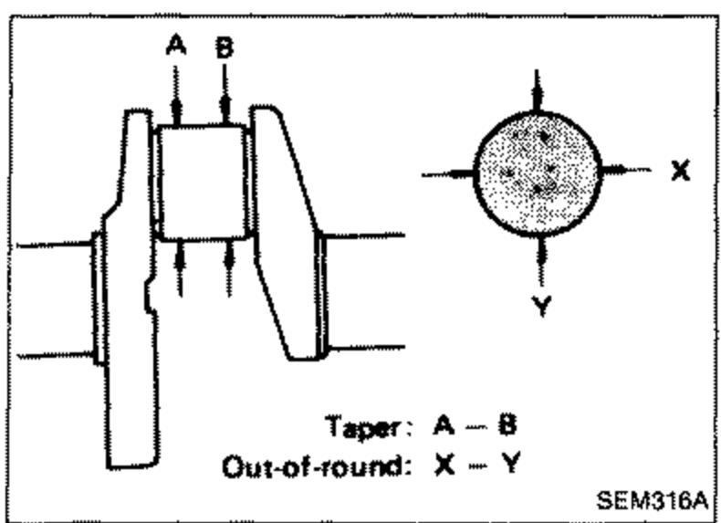
- 2With a micrometer, measure journals for taper and out-of-round.
 SEM316A
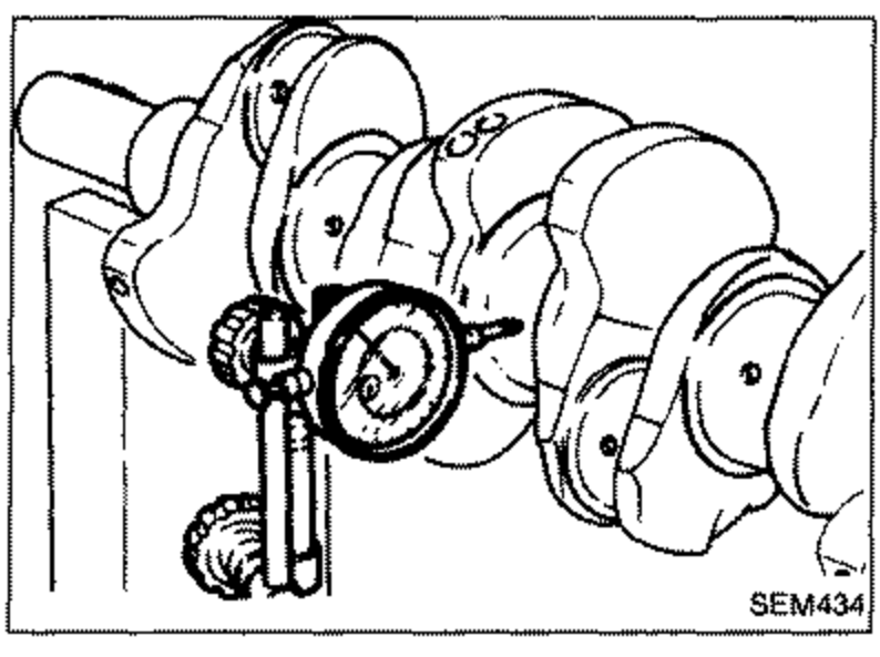
 - 3Measure crankshaft runout.Runout (Total indicator reading): Less than 0.05 mm (0.0020 in)
 SEM434
Out-of-round (X-Y) and Taper (A-B) - Unit: mm (in)
Main journal
SR20DELess than 0.005 (0.0002)
SR20DETLess than 0.005 (0.0002)
Pin journal
SR20DELess than 0.005 (0.0002)
SR20DETLess than 0.0025 (0.0001)
BEARING CLEARANCE
Either of the following two methods may be used, however, method "A" gives more reliable results and is preferable.
Method A (Using bore gauge & micrometer)
Main bearing
Method A (Using bore gauge & micrometer) - Main bearing
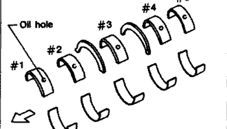
- 1Set main bearings in their proper positions on cylinder block and main bearing cap.
 SEM685D
 - 2Install main bearing cap and main bearing beam to cylinder block.Tighten all bolts in correct order in two or three stages.
 SEM100D
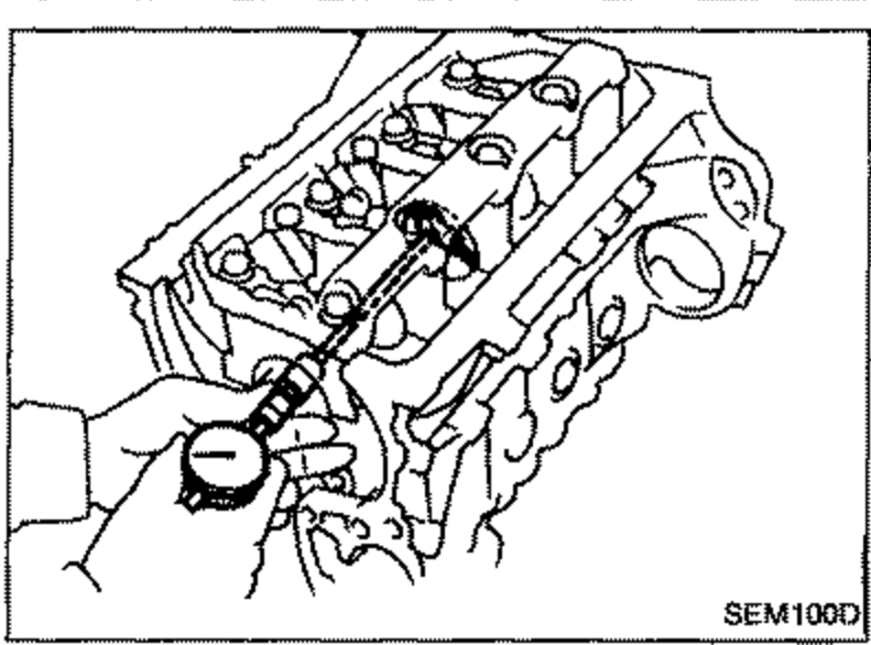
 - 3Measure inner diameter "A" of each main bearing.