
CYLINDER HEAD
EM-42prose procedureInspection (Cont'd)
VALVE GUIDE CLEARANCE (continued)
- 2If it exceeds the limit, check valve to valve guide clearance.
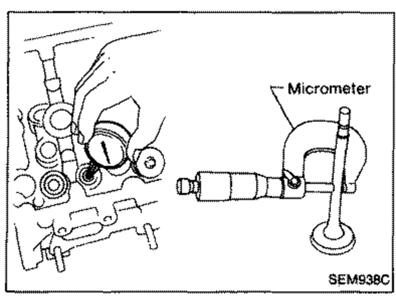
- 3a. Measure valve stem diameter and valve guide inner diameter. b. Check that clearance is within specification.
 SEM038C
 - 4c. If it exceeds the limit, replace valve or valve guide.
Valve to valve guide clearance (Unit: mm (in))
Intake
Standard0.020 - 0.050 (0.0008 - 0.0020)
Limit0.1 (0.004)
Exhaust
Standard0.040 - 0.070 (0.0016 - 0.0028)
Limit0.1 (0.004)
VALVE GUIDE REPLACEMENT
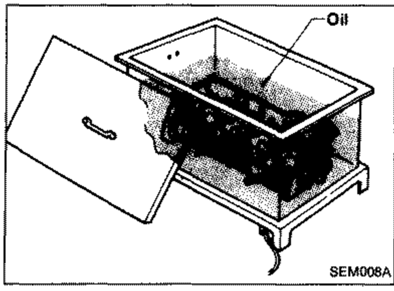
- 1To remove valve guide, heat cylinder head to 110 to 120°C (230 to 248°F).
 SEM008A
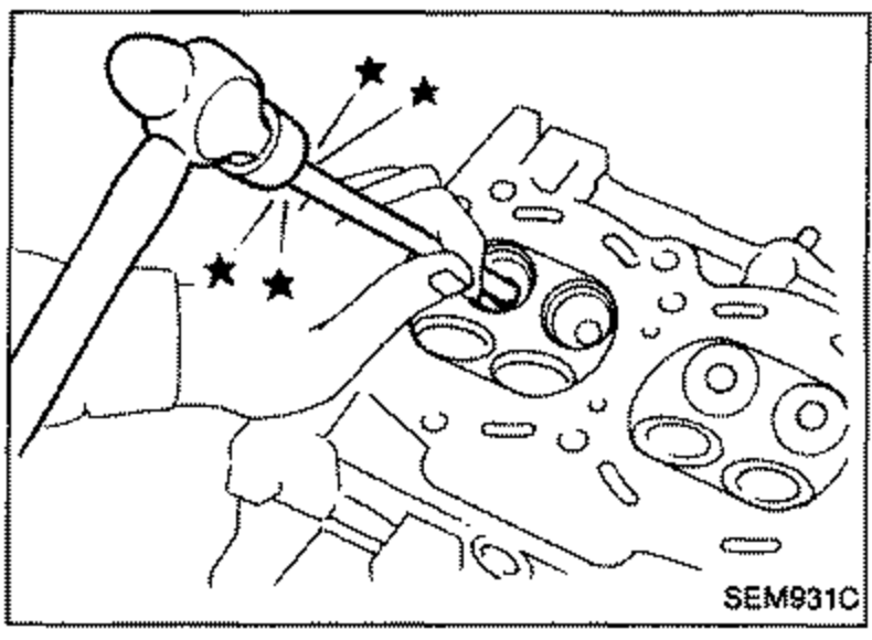
 - 2Drive out valve guide with a press [under a 20 kN (2 t, 2.2 US ton, 2.0 Imp ton) pressure] or hammer and suitable tool.
 SEM931C
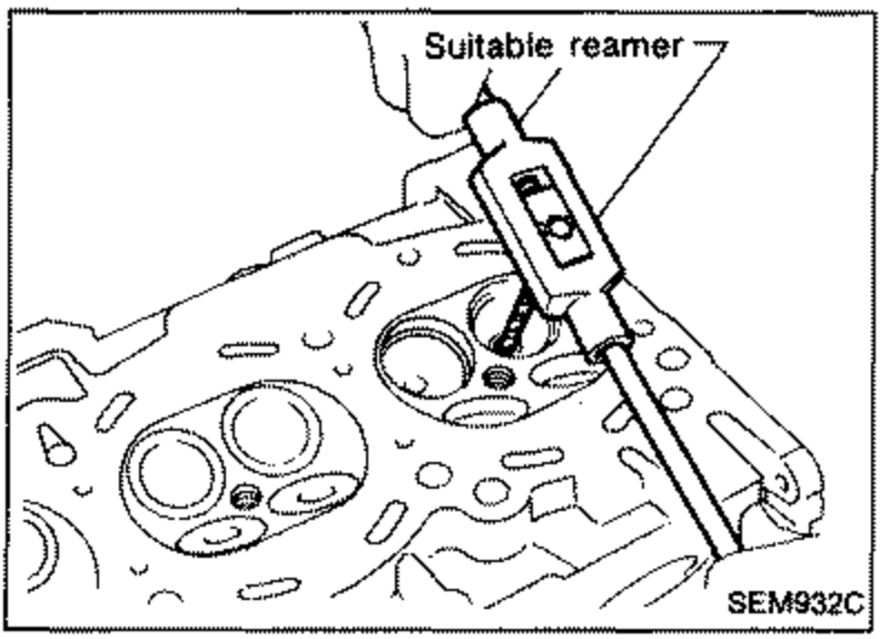
 - 3Ream cylinder head valve guide hole. Valve guide hole diameter (for service parts): Intake & Exhaust 9.685 - 9.696 mm (0.3813 - 0.3817 in).
 SEM932C
| Specification | Value |
|---|---|
| Valve guide hole diameter (for service parts) - Intake & Exhaust0.3813 - 0.3817 in | 9.685 - 9.696mm |
Valve guide hole diameter (for service parts) - Intake & Exhaust0.3813 - 0.3817 in
9.685 - 9.696mm