
Cylinder Head - Inspection (Valve Lifter, Combustion Chamber, Camshaft)
EM-223prose procedureValve lifter guide bore, clearance and camshaft end play differ between CD17 and CD20.
CYLINDER HEAD — Inspection
Valve Lifter (continued)
- 2Check diameter of valve lifters. Outer diameter: 34.959 - 34.975 mm (1.3763 - 1.3770 in)
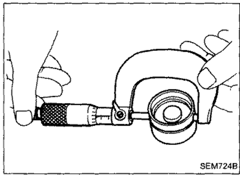 SEM724B
 - 3Check valve lifter guide bore. CD17 — Bore diameter 34.988 - 35.013 mm (1.3775 - 1.3785 in), Standard clearance 0.013 - 0.054 mm (0.0005 - 0.0021 in); CD20 — Bore diameter 34.998 - 35.018 mm (1.3779 - 1.3787 in), Standard clearance 0.023 - 0.059 mm (0.0009 - 0.0023 in)
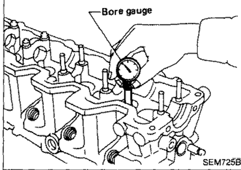 SEM725B
| Specification | Value |
|---|---|
| Valve lifter outer diameter1.3763 - 1.3770 in | 34.959 - 34.975mm |
| CD17 valve lifter guide bore diameter1.3775 - 1.3785 in | 34.988 - 35.013mm |
| CD17 standard clearance0.0005 - 0.0021 in | 0.013 - 0.054mm |
| CD20 valve lifter guide bore diameter1.3779 - 1.3787 in | 34.998 - 35.018mm |
| CD20 standard clearance0.0009 - 0.0023 in | 0.023 - 0.059mm |
Valve lifter outer diameter1.3763 - 1.3770 in
34.959 - 34.975mm
CD17 valve lifter guide bore diameter1.3775 - 1.3785 in
34.988 - 35.013mm
CD17 standard clearance0.0005 - 0.0021 in
0.013 - 0.054mm
CD20 valve lifter guide bore diameter1.3779 - 1.3787 in
34.998 - 35.018mm
CD20 standard clearance0.0009 - 0.0023 in
0.023 - 0.059mm
COMBUSTION CHAMBER REPLACEMENT
IMPORTANT
Usually combustion chambers should not be removed. However, if they show cracks or extensive damage, they should be replaced.
Combustion Chamber Replacement
- 1Remove glow plug connecting plate, glow plugs and injection nozzle.
- 2Heat cylinder head in oil to between 150 and 160°C (302 and 320°F).
- 3Remove combustion chamber so that cylinder head will not be damaged.Be careful not to scratch inside of nozzle hole.
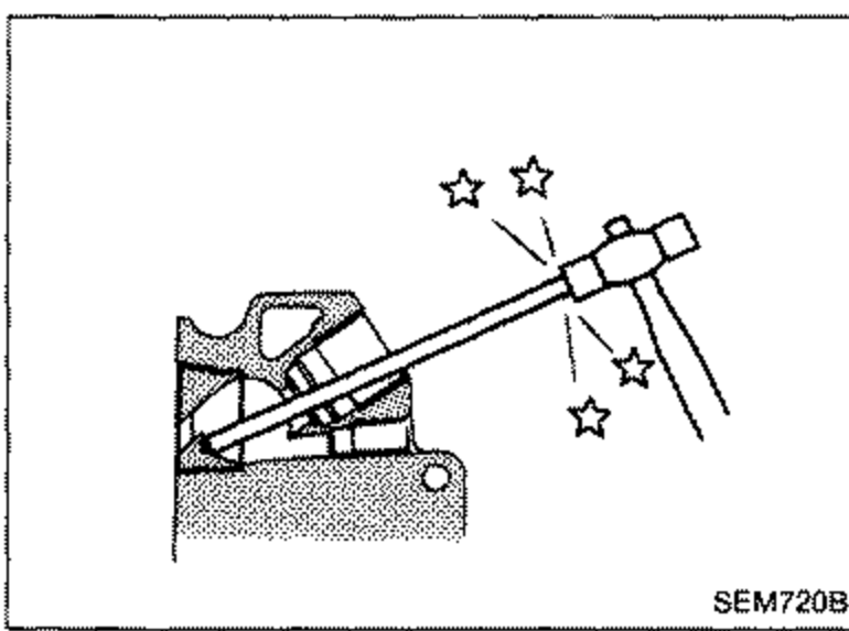 SEM720B
 - 4Install combustion chamber.a. Heat cylinder head 150 to 160°C (302 to 320°F) in oil.b. Align combustion chamber knock pin with cylinder head notch, and install it into cylinder head using a plastic-tip hammer.
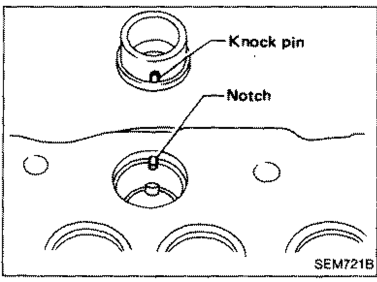 SEM721B
CAMSHAFT VISUAL CHECK
Check camshaft for scratches, seizure and wear.
Camshaft End Play
- 1Install camshaft in cylinder head.
- 2Tighten bracket bolts to the specified torque.
- 3Measure camshaft end play. Camshaft end play: Standard CD17 0.06 - 0.17 mm (0.0024 - 0.0067 in); CD20 0.115 - 0.188 mm (0.0045 - 0.0074 in)
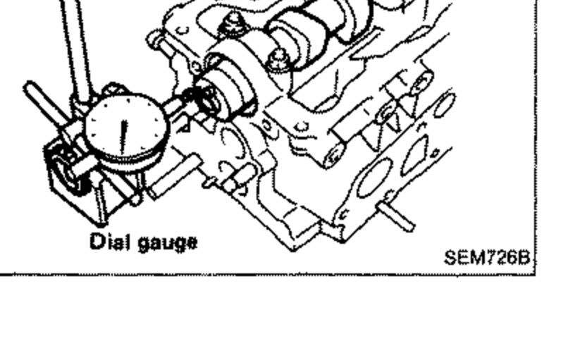 SEM726B
| Specification | Value |
|---|---|
| Camshaft end play, Standard CD170.0024 - 0.0067 in | 0.06 - 0.17mm |
| Camshaft end play, Standard CD200.0045 - 0.0074 in | 0.115 - 0.188mm |
Camshaft end play, Standard CD170.0024 - 0.0067 in
0.06 - 0.17mm
Camshaft end play, Standard CD200.0045 - 0.0074 in
0.115 - 0.188mm