
E.G.R. SYSTEM - Inspection (Cont'd)
EF & EC-721prose procedureThrottle chamber control valve check applies to CD20 only.
Inspection (Cont'd)
THROTTLE CHAMBER CONTROL VALVE — CD20
Ensure that throttle chamber control valve is held (closed) at stopper when a vacuum pressure of approximately greater than -13.3 kPa (-133 mbar, -100 mmHg, -3.94 inHg) is applied from a vacuum handy pump to vacuum port.
E.G.R. CONTROL SOLENOID VALVES
Check the solenoid valves for normal operation, after disconnecting the connector and all the vacuum hoses.
Supply the solenoid valves with battery voltage, and check whether there is continuity between ports A, B and C.
E.G.R. control solenoid valve continuity
Continuity
OFFA-C
ONA-B
| Specification | Value |
|---|---|
| Resistance | Approx. 35Ω |
Resistance
Approx. 35Ω
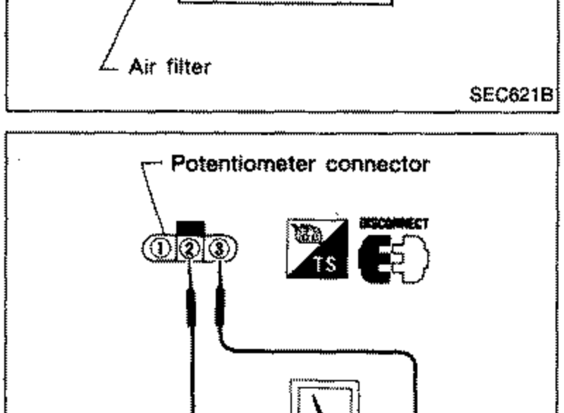
POTENTIOMETER
- 1Disconnect potentiometer connector and connect ohmmeter as shown.
 SEC646B
 - 2Make sure that the resistance changes when the control lever opening angle of the fuel injection pump is changed.
| Specification | Value |
|---|---|
| ResistanceBetween terminals 1 and 3 | 1 - 3 Approx. 5kΩ |
ResistanceBetween terminals 1 and 3
1 - 3 Approx. 5kΩ
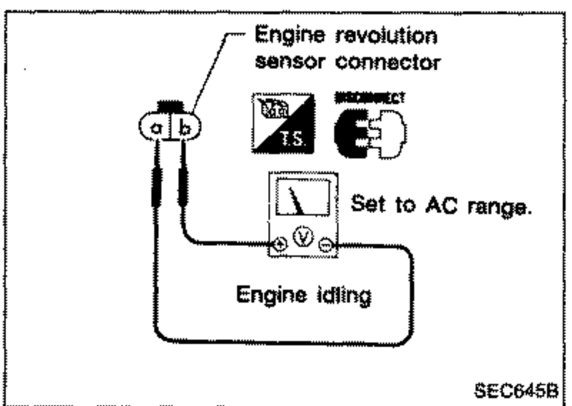
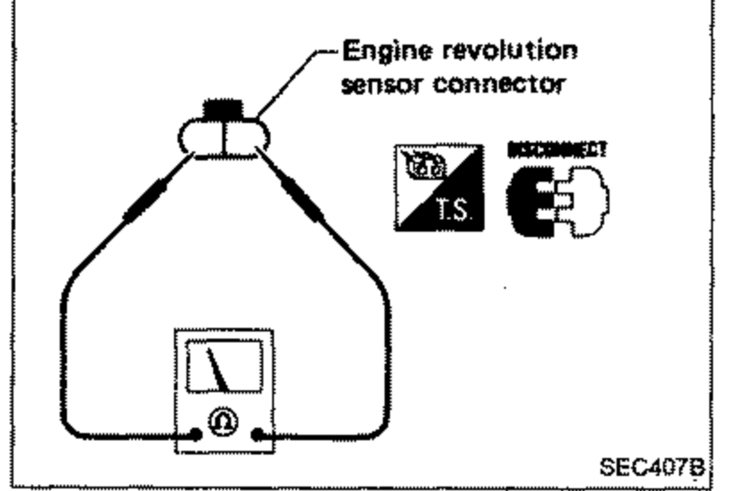
ENGINE REVOLUTION SENSOR
- 1While idling engine, check AC voltage across terminal a and b.
 SEC645B
 - 2If voltage is not within specifications, conduct a continuity test.
 SEC407B
 - 3Read pulse.
| Specification | Value |
|---|---|
| Engine idlingAC voltage; increases as engine speed is increased | Approx. 0.8V |
| Resistancecontinuity established | Approx. 1.36 - 1.84kΩ |
| Pulse | 37 pulses/8 engine revolutions |
Engine idlingAC voltage; increases as engine speed is increased
Approx. 0.8V
Resistancecontinuity established
Approx. 1.36 - 1.84kΩ
Pulse
37 pulses/8 engine revolutions