
Electrical Components Inspection (Cont'd)
EF & EC-629prose procedureAir flow meter idle voltage differs: SR20DE 1.3 - 1.8V vs SR20DET 1.0 - 1.5V.
TROUBLE DIAGNOSES
Electrical Components Inspection (Cont'd)
CRANK ANGLE SENSOR
- 1Remove distributor from engine. (Crank angle sensor harness connector should remain connected.)
- 2Disconnect ignition wires.
- 3Turn ignition switch "ON".
- 4Rotate distributor shaft slowly by hand and check voltage between terminals ⓐ, ⓓ and ground.
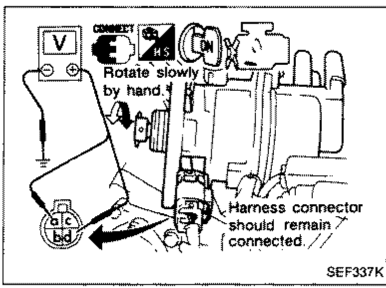 SEF337K
 - 5Visually check signal plate for damage or dust.
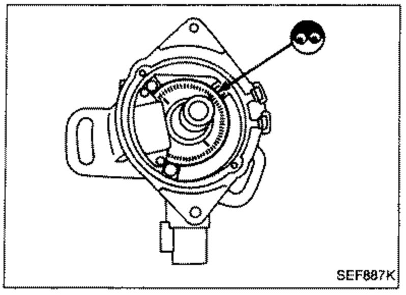 SEF887K
Crank angle sensor voltage
ⓐ (180° signal)
VoltageTester's pointer fluctuates between 5V and 0V.
ⓓ (1° signal)
VoltageTester's pointer fluctuates between 5V and 0V.
If N.G., replace distributor assembly with crank angle sensor.
AIR FLOW METER
- 1Peel air flow meter harness connector rubber as shown in the figure if the harness connector is connected.
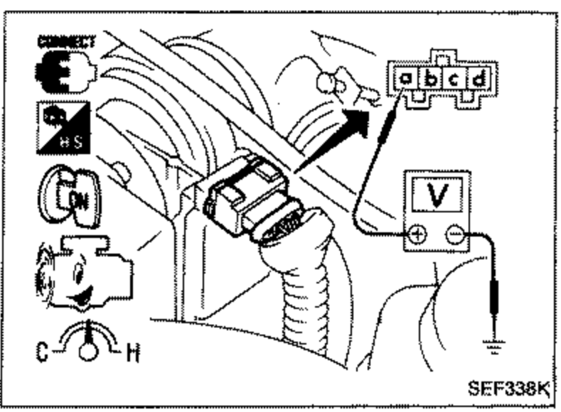 SEF338K
 - 2Turn ignition switch "ON".
- 3Start engine and warm it up sufficiently.
- 4Check voltage between terminal ⓐ and ground.
Air flow meter voltage
Ignition switch "ON" (Engine stopped.)
Voltage VLess than 1.0
Idle (Engine is warmed-up sufficiently.)
Voltage VSR20DE: 1.3 - 1.8V / SR20DET: 1.0 - 1.5V