
VE-TYPE INJECTION PUMP — Testing of Injection Pump (Cont'd)
EF & EC-695prose procedureInjection timing mark differs by engine: CD17 11° ATDC, CD20 9° ATDC. VE-type injection pump applies to CD diesel engines.
Testing of Injection Pump (Cont'd)
Cold start device adjustment (continued)
- 6Select feeler gauge whose thickness equals the specified clearance [obtained from S.D.S.: ℓ ± 0.05 mm (0.0020 in)] between idle adjusting screw and control lever.
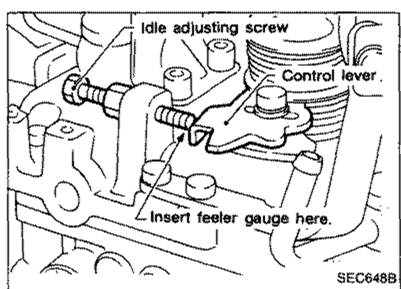 SEC648B
 - 7Insert the feeler gauge between idle adjusting screw and control lever.
- 8Turn cold start linkage screw C such that fast idle adjusting screw F slightly contacts control lever.
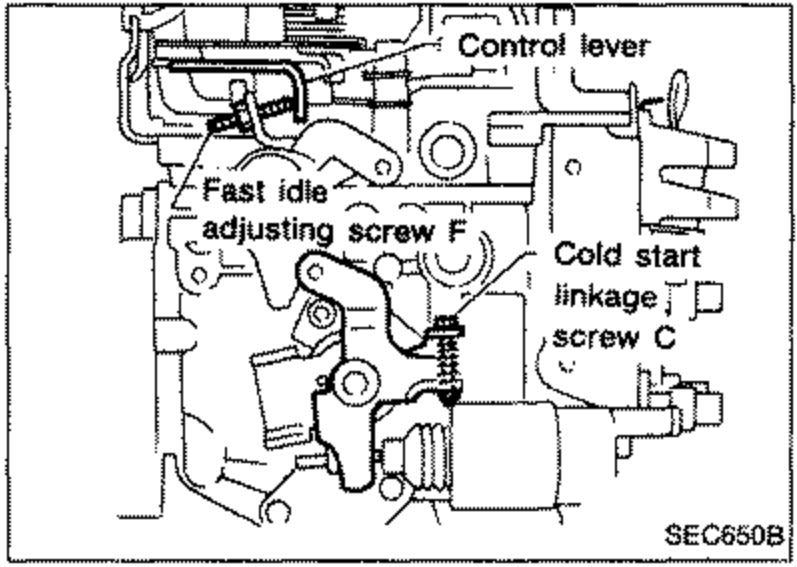 SEC650B
Installation
- 1Set No. 1 piston at injection timing mark on its compression stroke.Injection timing mark: Yellow painted markCD17: 11° ATDCCD20: 9° ATDC
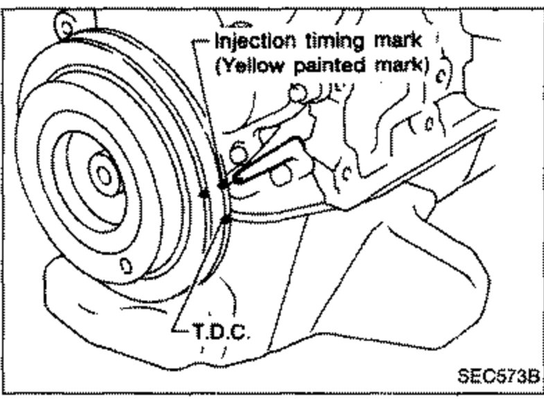 SEC573B
 - 2Install injection pump and timing belt.Refer to MA section for installing timing belt.Temporarily secure injection pump bolts so alignment mark on injection pump flange meets the mark on injection pump bracket.
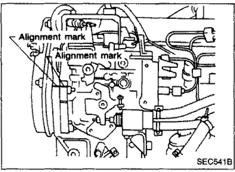 SEC541B
 - 3Adjust injection timing.
Adjustment
INJECTION TIMING ADJUSTMENT (Plunger lift adjustment)
Preparation of cold start device
- 1Turn cold start device linkage clockwise.
- 2Set a suitable block [Thickness: about 15 mm (0.59 in)] between cold start device plunger and linkage rod.
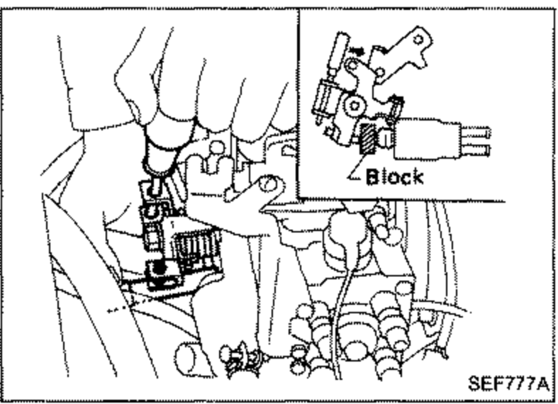 SEF777A
 - 3Turn crankshaft 2 turns clockwise to set the device to normal position.