
E.C.C. TROUBLE DIAGNOSES (Models with catalyzer) — Electrical Components Inspection (Cont'd)
EF & EC-144flowchartGA13DS, GA14DS & GA16DS engines (models with catalyzer).
Electrical Components Inspection (Cont'd)
POWER TRANSISTOR
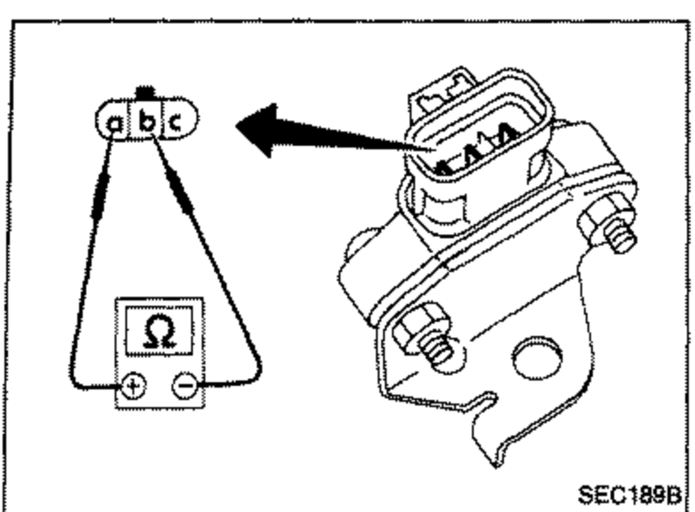
- 1Disconnect power transistor harness connector.
 SEC189B
 - 2Check power transistor continuity between terminals as shown in the illustration.
Power transistor continuity check
1
⊕ side: ⓐ, ⊖ side: ⓑ — Resistance: ∞ Ω
N.G.
Replace power transistor unit.
O.K.
2
⊕ side: ⓑ, ⊖ side: ⓐ — Resistance: ∞ Ω
N.G.
same as step 1
O.K.
3
⊕ side: ⓑ, ⊖ side: ⓒ — Resistance: Not ∞ or 0Ω
N.G.
same as step 1
O.K.
4
⊕ side: ⓒ, ⊖ side: ⓑ — Resistance: Not ∞ or 0Ω
N.G.
same as step 1
O.K.
5
⊕ side: ⓒ, ⊖ side: ⓐ — Resistance: Not ∞ or 0Ω
N.G.
same as step 1
O.K.
6
⊕ side: ⓒ, ⊖ side: ⓐ — Resistance: Not ∞ or 0Ω
N.G.
same as step 1
O.K.
INSPECTION END
BOOST PRESSURE SENSOR
- 1Turn ignition switch "ON".
- 2Start engine.
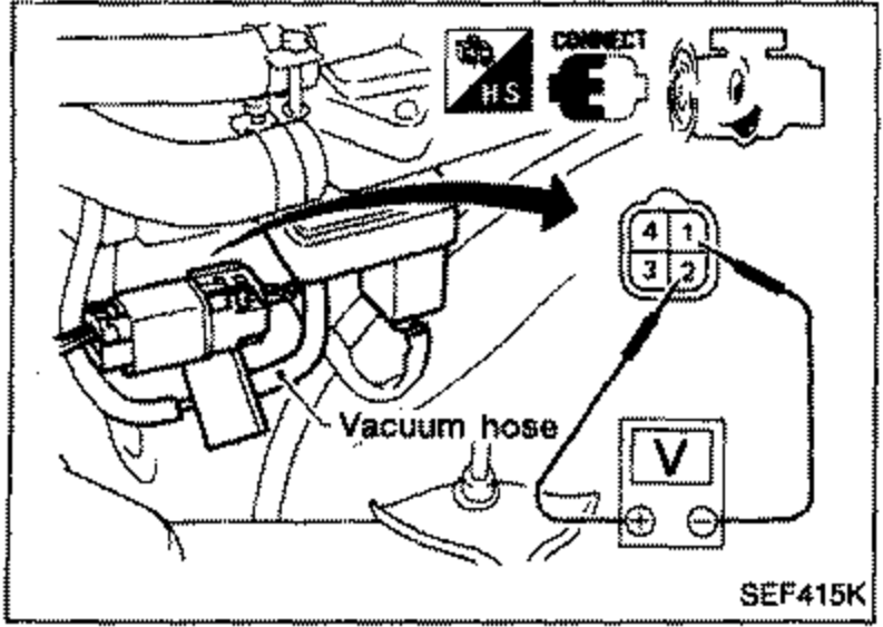
- 3Check voltage between ① and ②.
 SEF415K
Boost pressure sensor voltage
Vacuum hose connected
VoltageApproximately 1.0V
Vacuum hose disconnected
VoltageApproximately 4.0V
If N.G., replace boost pressure sensor.