
CARBURETOR - Dash Pot or F.I. (Fast Idle) Pot (Cont'd) / Throttle Valve Switch (Models with catalyzer)
EF & EC-174prose procedureM/T vs A/T idle speed specs differ (750 ± 50 vs 850 ± 50 in "N"). Models with vs without catalyzer differ in idle CO% and throttle valve switch procedure applies only to models with catalyzer.
Dash Pot or F.I. (Fast Idle) Pot (Cont'd)
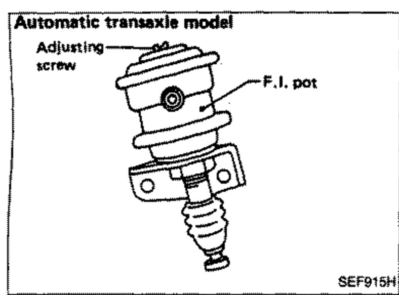
F.I. ACTUATOR
- 1Warm up engine sufficiently.
- 2Check idle speed and mixture ratio.Idle speed: rpm (in "N" position) M/T 750 ± 50; A/T 850 ± 50Idle "CO": 1.5 ± 0.5% (Models without catalyzer); 1.0 ± 0.5%* (Models with catalyzer)* Disconnect exhaust gas sensor harness connector and A.I.V. control solenoid valve connector.
 SEF915H
 - 3Turn air conditioner switch "ON", and check idle speed.Idle speed: rpm (in "N" position) M/T 850 ± 50; A/T 850 ± 50
- 4If out of specification, adjust idle speed by turning adjusting screw.
| Specification | Value |
|---|---|
| Idle speed (in "N" position), M/TCheck idle speed and mixture ratio | 750 ± 50rpm |
| Idle speed (in "N" position), A/TCheck idle speed and mixture ratio | 850 ± 50rpm |
| Idle "CO" (Models without catalyzer) | 1.5 ± 0.5% |
| Idle "CO" (Models with catalyzer)Disconnect exhaust gas sensor harness connector and A.I.V. control solenoid valve connector | 1.0 ± 0.5% |
| Idle speed with A/C ON (in "N" position), M/TAir conditioner switch "ON" | 850 ± 50rpm |
| Idle speed with A/C ON (in "N" position), A/TAir conditioner switch "ON" | 850 ± 50rpm |
Idle speed (in "N" position), M/TCheck idle speed and mixture ratio
750 ± 50rpm
Idle speed (in "N" position), A/TCheck idle speed and mixture ratio
850 ± 50rpm
Idle "CO" (Models without catalyzer)
1.5 ± 0.5%
Idle "CO" (Models with catalyzer)Disconnect exhaust gas sensor harness connector and A.I.V. control solenoid valve connector
1.0 ± 0.5%
Idle speed with A/C ON (in "N" position), M/TAir conditioner switch "ON"
850 ± 50rpm
Idle speed with A/C ON (in "N" position), A/TAir conditioner switch "ON"
850 ± 50rpm
Throttle Valve Switch (Models with catalyzer)
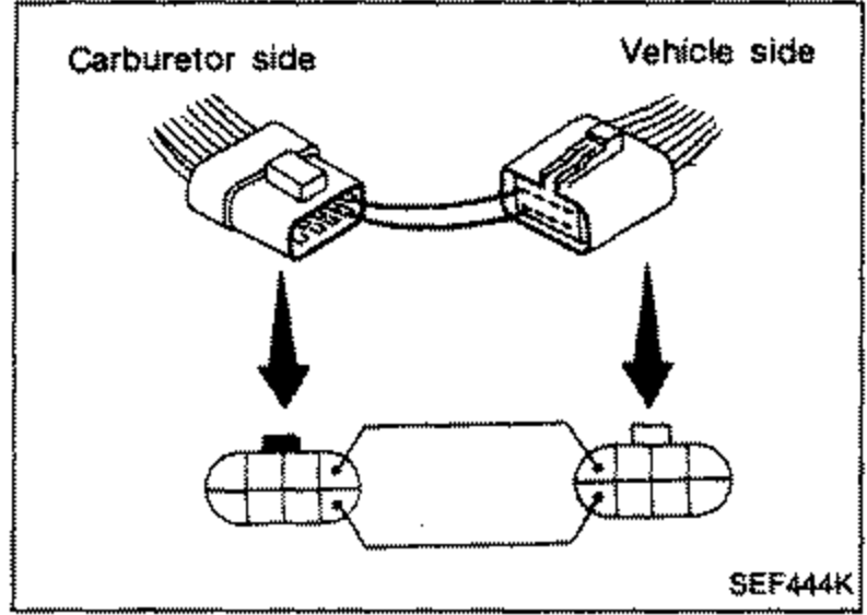
- 1Turn off engine and disconnect harness connector on carburetor.
 SEF444K
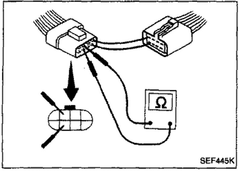
 - 2Connect proper wires between the fuel cut solenoid valve harness terminals.
- 3Verify that continuity does not exist between the throttle valve switch harness terminals.
 SEF445K
 - 4Start engine and increase engine speed to about 2,000 rpm.
- 5At this time, verify that continuity exists between the throttle valve harness terminals.
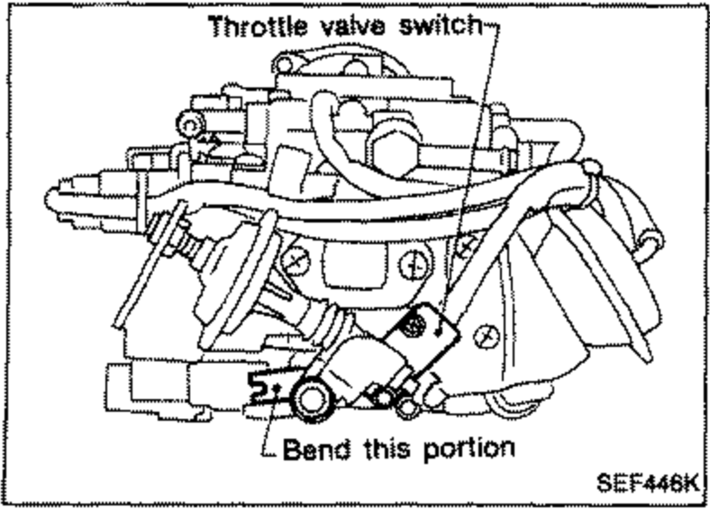
- 6Then, decrease engine speed gradually to below. Engine speed: 1,200 rpm. At that point, the circuit should break and cause the ohmmeter to indicate an open circuit. If incorrect, adjust by bending plate until the ohmmeter indicates an open circuit.Engine speed: 1,200 rpm
 SEF446K