
ENGINE AND EMISSION CONTROL PARTS LOCATION — Models With Catalyzer and E.G.R.
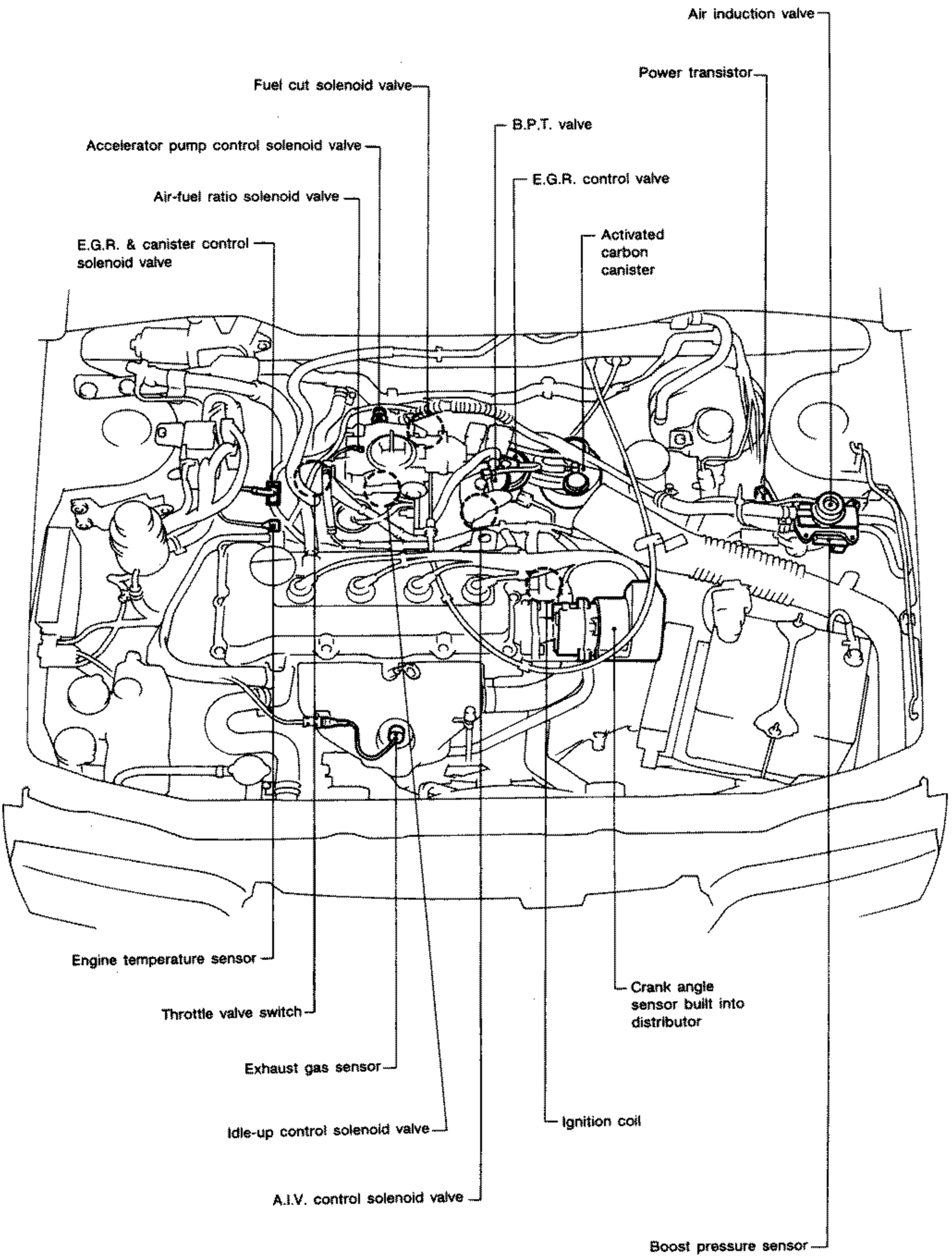
EF & EC-10component photoGA13DS/GA14DS/GA16DS engines, models with catalyzer and E.G.R.
Models With Catalyzer and E.G.R.
Component LocationFig. fig1
Engine compartment layout for models with catalyzer and E.G.R. (SEF356L).
SEF356L
1Air induction valve(top right)
2Power transistor(top right)
3Fuel cut solenoid valve(top left)
4B.P.T. valve(top center)
5Accelerator pump control solenoid valve(upper left)
6E.G.R. control valve(top center)
7Air-fuel ratio solenoid valve(upper left)
8Activated carbon canister(upper right)
9E.G.R. & canister control solenoid valve(upper left)
10Engine temperature sensor(lower left)
11Throttle valve switch(lower left)
12Exhaust gas sensor(lower center-left)
13Idle-up control solenoid valve(lower center)
14A.I.V. control solenoid valve(lower center)
15Ignition coil(lower center)
16Crank angle sensor built into distributor(lower right)
17Boost pressure sensor(lower right)