
E.C.C. Trouble Diagnoses (Models with catalyzer) - Diagnostic Procedure (Cont'd)
EF & EC-49prose procedureApplies to GA13DS, GA14DS & GA16DS engines with catalyzer.
Diagnostic Procedure (Cont'd)
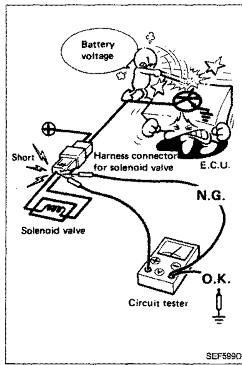
- 6When measuring supply voltage of E.C.U. controlled components with a circuit tester, separate one tester probe from the other. If the two tester probes accidentally make contact with each other during measurement, the circuit will be shorted, resulting in damage to the power transistor of the control unit.If the two tester probes accidentally make contact, the circuit will be shorted, damaging the power transistor of the control unit.
 SEF599O
 - 7When measuring voltage or resistance at connector with tester probes, there are two methods of measurement; one is done from terminal side and the other from harness side. Before measuring, confirm symbol mark again. (HS symbol): Inspection should be done from harness side. (TS symbol): Inspection should be done from terminal side. Refer to GI section.
- 8As for continuity check of joint connector, refer to EL section.
- 9Key to symbols: (DISCONNECT symbol): Check after disconnecting the connector to be measured. (CONNECT symbol): Check after connecting the connector to be measured.
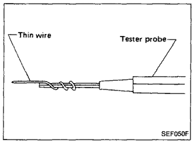
- 10Improve tester probe as shown to perform test easily.
 SEF050F
 - 11For the first trouble-shooting procedure, perform POWER SOURCE & GROUND CIRCUIT FOR E.C.C. control unit check.