
TROUBLE DIAGNOSES — Diagnostic Procedure
EF & EC-249prose procedureDiagnostic Procedure
- 1Before connecting or disconnecting the E.C.U. harness connector to or from any E.C.U., be sure to turn the ignition switch to the "OFF" position and disconnect the negative battery terminal in order not to damage E.C.U. as battery voltage is applied to E.C.U. even if ignition switch is turned off. Failure to do so may damage the E.C.U.CAUTION
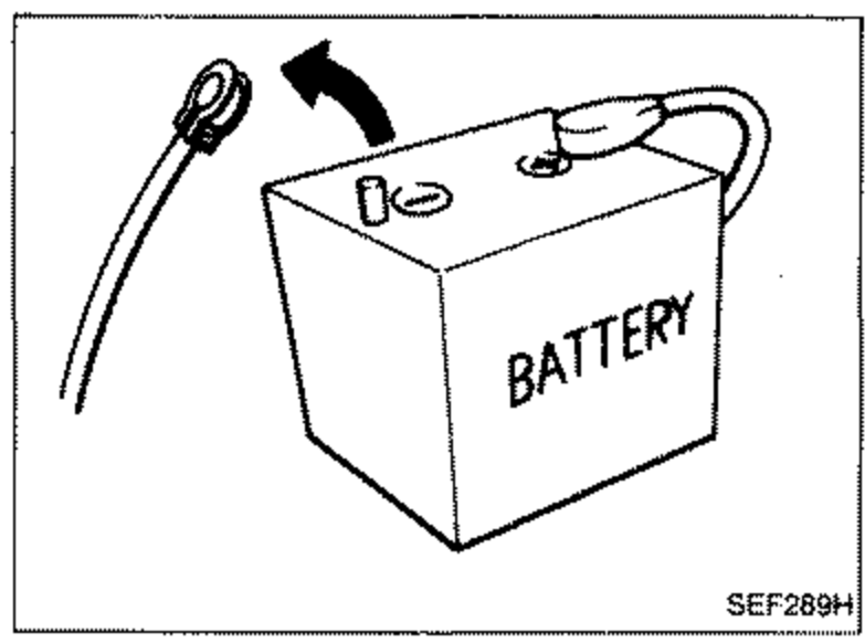 SEF289H
 - 2When connecting E.C.U. harness connector, tighten securing bolt until red projection is in line with connector face.
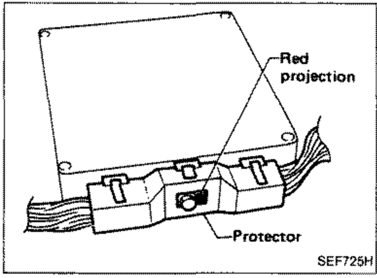 SEF725H
 - 3When connecting or disconnecting pin connectors into or from E.C.U., take care not to damage pin terminals (bend or break).
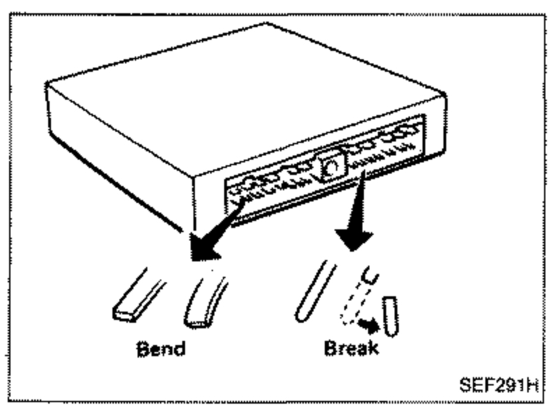 SEF291H
 - 4Make sure that there are not any bends or breaks on E.C.U. pin terminal, when connecting pin connectors.
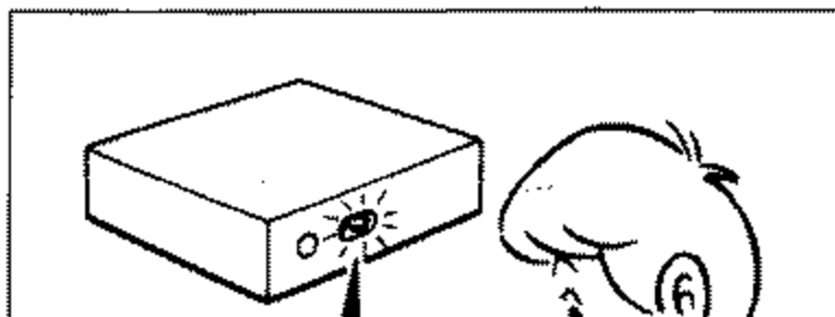
- 5Before replacing E.C.U., perform E.C.U. input/output signal inspection and make sure whether E.C.U. functions properly or not. (See page EF & EC-343.)
 SEF330D
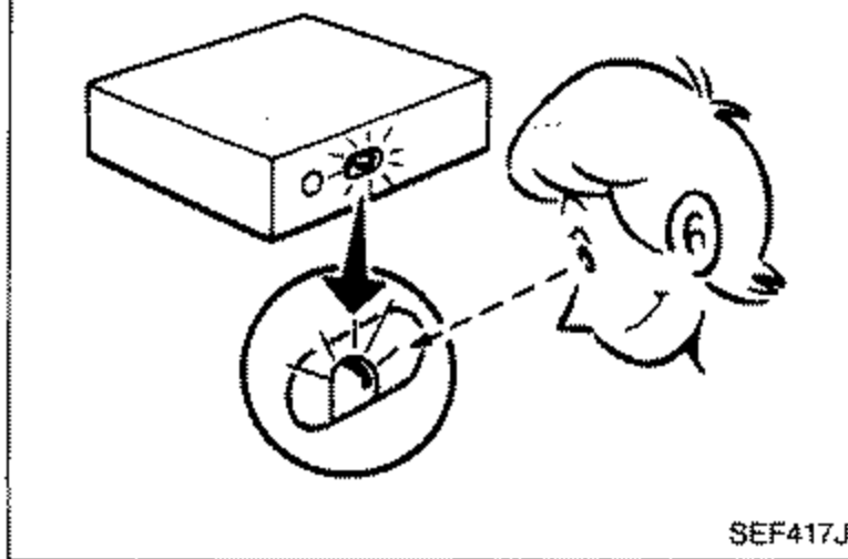
 - 6After performing this "Diagnostic Procedure", perform E.C.C.S. self-diagnosis and driving test.
 SEF417J