
E.C.C. TROUBLE DIAGNOSES (Models with catalyzer) — Electrical Components Inspection (Cont'd)
EF & EC-148prose procedureGA13DS, GA14DS & GA16DS engines (models with catalyzer).
Electrical Components Inspection (Cont'd)
EXHAUST GAS SENSOR
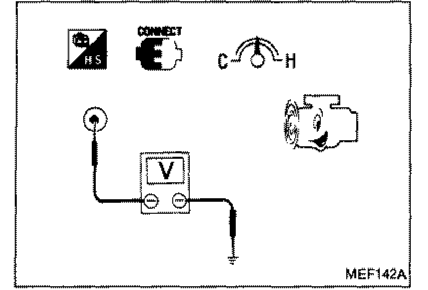
- 1Start engine and warm it up until water temperature indicator points to middle of gauge.
 MEF142A
 - 2Run engine at about 2,000 rpm for about 2 minutes under no-load.
- 3Check voltage between terminal Ⓐ and ground. Make sure that needle of voltmeter fluctuates between approx. 0 and 1V, more than 5 times in 10 seconds at 2,000 rpm. If N.G., replace exhaust gas sensor.
AIR INDUCTION VALVE (A.I.V.)
- 1Disconnect vacuum hoses.
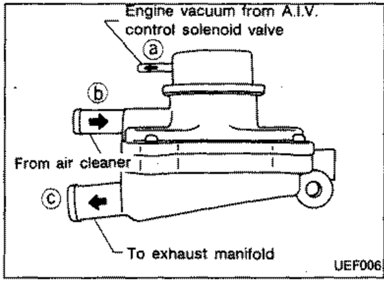
- 2Check air flow between Ⓑ and Ⓒ in the following situations:a. No vacuum at Ⓐ. No air flow exists at Ⓒ.b. Vacuum at Ⓐ. Air flow exists at Ⓒ.c. No air flow at Ⓑ. With or without vacuum at Ⓐ.
 UEF006