
E.C.C. TROUBLE DIAGNOSES (Models with catalyzer) — Electrical Components Inspection (Cont'd): Crank Angle Sensor, Engine Temperature Sensor, Ignition Coil, Inhibitor Switch
EF & EC-143prose procedureComponent inspection procedures; engines GA13DS, GA14DS & GA16DS with catalyzer. Inhibitor switch implies A/T application.
GA13DS, GA14DS & GA16DS
Electrical Components Inspection (Cont'd)
Crank Angle Sensor
- 1Remove distributor from engine. (Crank angle sensor harness connector should remain connected.)
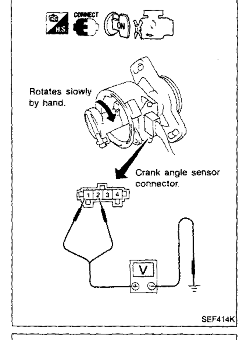 SEF414K
 - 2Disconnect ignition wires.
- 3Turn ignition switch "ON".
- 4Rotate distributor shaft slowly by hand and check voltage between terminals 3, 4 and ground.If N.G., replace distributor assembly with crank angle sensor.
Crank Angle Sensor — Voltage
1 (180° signal)
VoltageTester's pointer fluctuates between 5V and 0V.
2 (1° signal)
VoltageTester's pointer fluctuates between 5V and 0V.
Engine Temperature Sensor
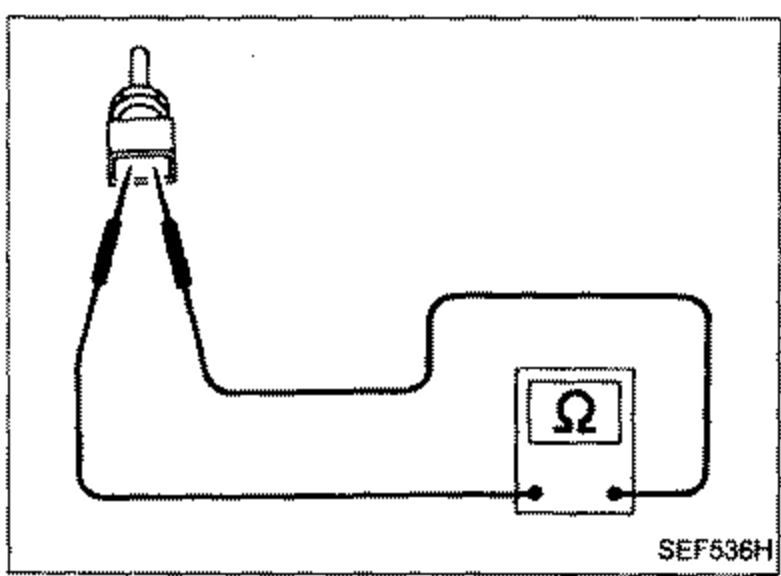
- 1Disconnect engine temperature sensor harness connector.
 SEF536H
 - 2Check resistance as shown in the figure.If N.G., replace engine temperature sensor.
Engine Temperature Sensor — Resistance
20 (68)
Resistance kΩ2.1 - 2.9
50 (122)
Resistance kΩ0.68 - 1.00
80 (176)
Resistance kΩ0.30 - 0.33
Ignition Coil
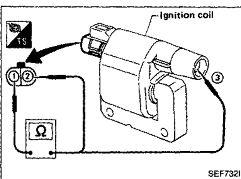
- 1Disconnect ignition coil harness connector.
 SEF732I
 - 2Check resistance as shown in the figure.If N.G., replace ignition coil.
Ignition Coil — Resistance
1 - 2
ResistanceApproximately 0.9Ω
1 - 3
ResistanceApproximately 9.5 kΩ
INHIBITOR SWITCH
Check continuity between terminals (a) and (b).
Inhibitor Switch — Continuity
Shift to "P" position
ContinuityYes
Shift to "N" position
ContinuityYes
Shift to position other than "P" and "N"
ContinuityNo
NOTE
If N.G., replace inhibitor switch.