
Electrical Components Inspection (Cont'd)
EF & EC-347prose procedureGA16DE engine (header tab).
Crank Angle Sensor
- 1Remove distributor from engine. (Crank angle sensor harness connector should remain connected.)
- 2Disconnect ignition wires.
- 3Turn ignition switch "ON".
- 4Rotate distributor shaft slowly by hand and check voltage between terminals ②, ① and ground.
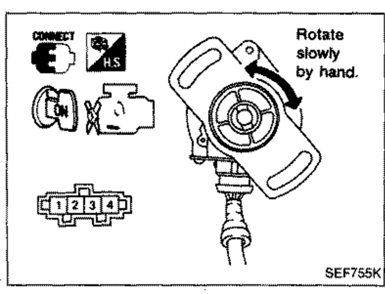 SEF755K
 - 5Visually check signal plate for damage or dust.
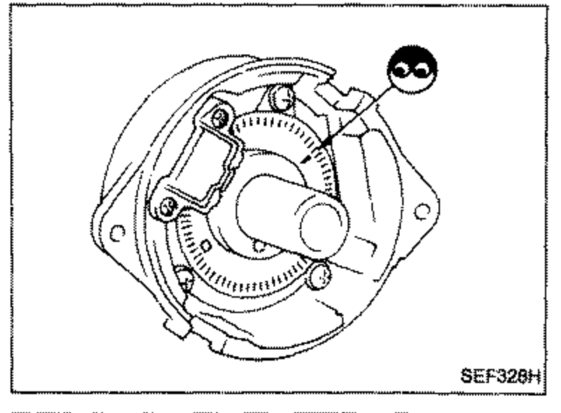 SEF328H
Crank Angle Sensor Voltage
① (180° signal)
VoltageTester's pointer fluctuates between 5V and 0V.
② (1° signal)
Voltage
If N.G., replace distributor assembly with crank angle sensor.
Air Flow Meter
- 1Peel air flow meter harness connector rubber as shown in the figure if the harness connector is connected.
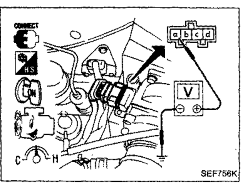 SEF756H
 - 2Turn ignition switch "ON".
- 3Start engine and warm it up sufficiently.
- 4Check voltage between terminal © and ground.
- 5If N.G., remove air flow meter from air duct. Check hot wire for damage or dust.
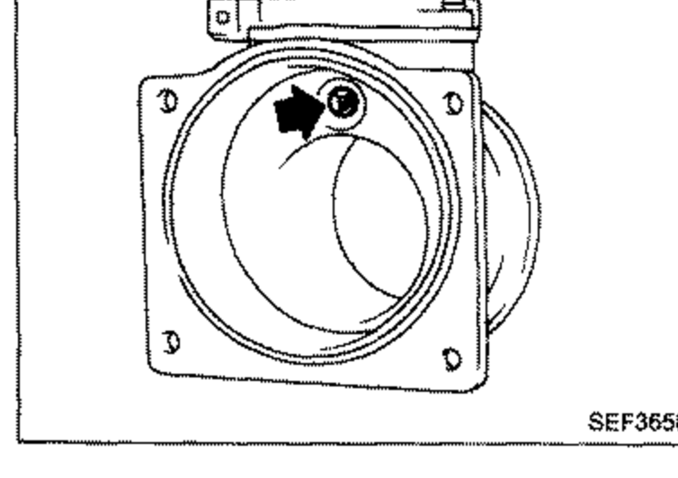 SEF365H
Air Flow Meter Voltage
Ignition switch "ON" (Engine stopped.)
Voltage VLess than 1.0
Idle (Engine is warm-up sufficiently.)
Voltage V0.7 - 1.1