
VE-TYPE INJECTION PUMP — Testing of Injection Pump (Cont'd)
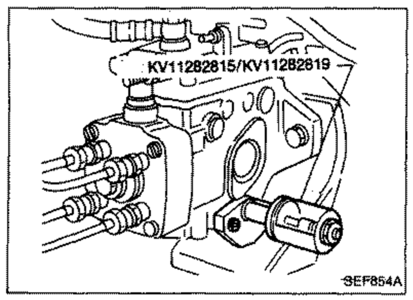
EF & EC-690prose procedureSpeed timer tool side selection depends on presence of cold start device.
Testing of Injection Pump (Cont'd)
- bWhen measured pressure is higher than specifications.
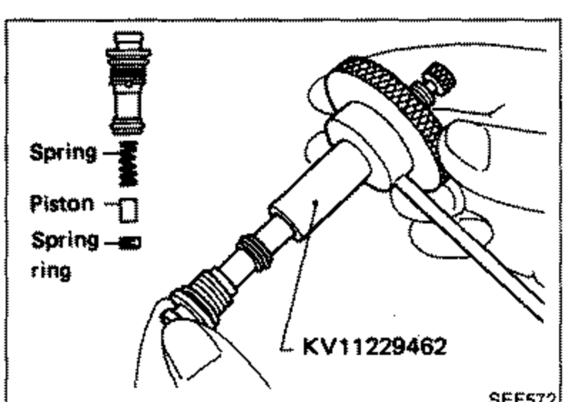
- 1Remove regulating valve from fuel injection pump, and disassemble regulating valve using Tool.
 SEF572
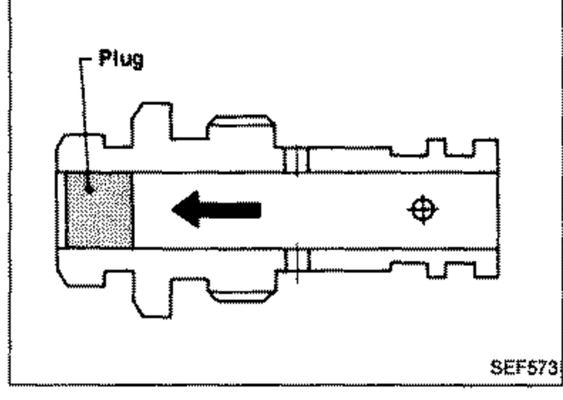
 - 2Drive plug out until it is flush with end face of regulating valve.
 SEF573
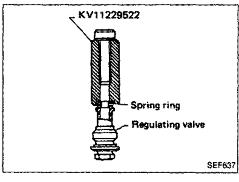
 - 3Install spring, piston and spring ring, in that order, to regulating valve. Make sure spring ring is flush with end face of regulating valve body when it is pushed in.
 SEF637
 - 4Attach regulating valve to fuel injection pump.
- 5Adjust feed pump pressure to specifications.
Adjustment of speed timer
- 1Remove cover of timer, and attach Tool to that side.Without cold start device: High pressure side (Side without spring)With cold start device: Low pressure side (Spring side)
 SEF854A