
Electrical Components Inspection (Cont'd)
EF & EC-634prose procedureAir regulator illustration differs between SR20DE (SEF292L) and SR20DET (SEF293L).
TROUBLE DIAGNOSES
Electrical Components Inspection (Cont'd)
F.I.C.D. SOLENOID VALVE (Cont'd)
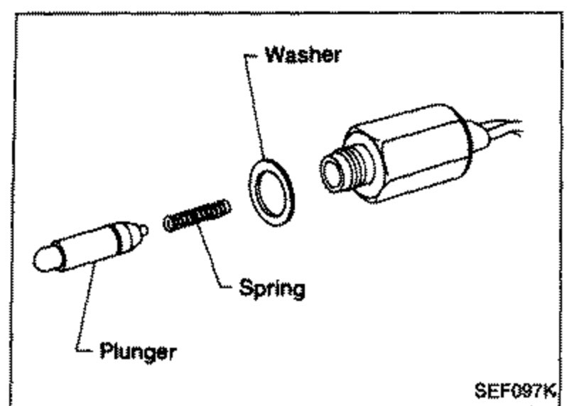
- 3Check plunger for seizing or sticking.
 SEF097K
 - 4Check for broken spring.
AIR REGULATOR
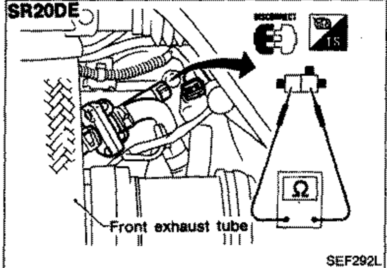
- 1Disconnect air regulator harness connector.
 SEF292L
 - 2Check air regulator resistance.
- 3Check air regulator for clogging.
| Specification | Value |
|---|---|
| Resistanceair regulator | Approximately 70 - 80Ω |
Resistanceair regulator
Approximately 70 - 80Ω
DETONATION SENSOR
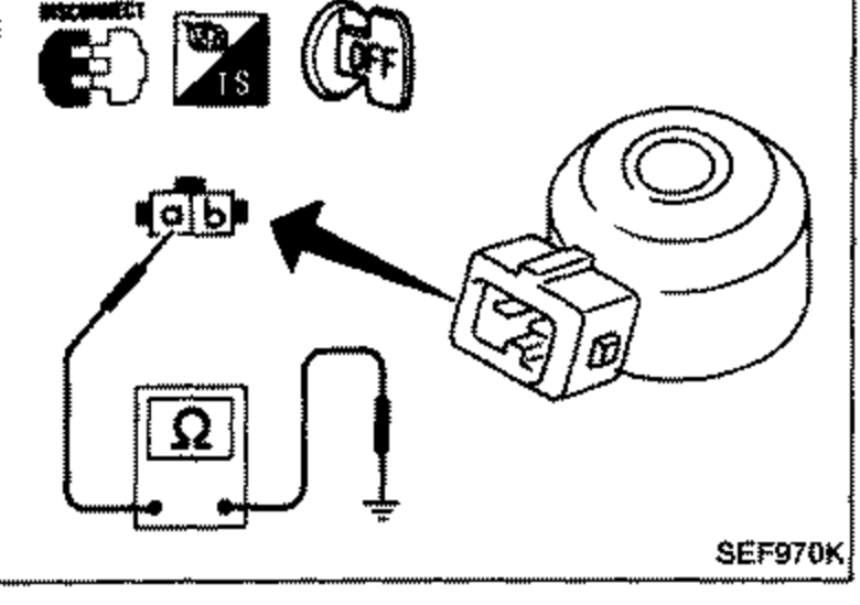
- 1Disconnect detonation sensor harness connector.
 SEF970K
 - 2Check continuity between terminal ⓐ and ground. Continuity should exist.It is necessary to use an ohmmeter which can measure more than 10 MΩ.
CAUTION
Discard any detonation sensor which has been dropped or undergone shocks; use a new one.
Installation
Install detonation sensor with connector side facing engine front.
When installing detonation sensor, ensure both upper and lower sides of detonation sensor and cylinder block mating surface are clean and free from foreign particles.
When tightening detonation sensor, be careful not to apply excessive force to connector.
Make sure detonation sensor is not in contact with any adjacent part after installing.