
FUEL INJECTION CONTROL SYSTEM INSPECTION
EF & EC-355prose procedureGA16DE engine (header tab).
Injector Removal and Installation (Cont'd)
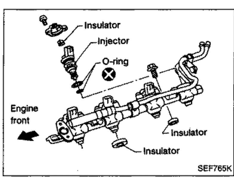
- 6Push out any malfunctioning injector from fuel tube assembly.Do not extract injector by pinching connector.
 SEF765K
 - 7Replace or clean injector as necessary.Always replace O-rings and insulators with new ones.Lubricate O-rings with a smear of silicone oil.
- 8Install injector to fuel tube assembly.
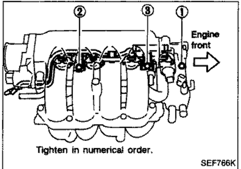
- 9Install injectors with fuel tube assembly to intake manifold. Tighten fuel tube bolts to the specified torque.Tightening procedure:1) Tighten all bolts to 9.3 to 10.8 N·m (0.95 to 1.1 kg-m, 6.9 to 8.0 ft-lb).2) Tighten all bolts to 16 to 21 N·m (1.6 to 2.1 kg-m, 12 - 15 ft-lb).
 SEF766K
 - 10Install fuel tubes to fuel tube assembly.Lubricate fuel tubes with a smear of silicone oil.
- 11Reinstall any parts removed in reverse order of removal.After properly connecting fuel hose to injector and fuel tube assembly, check connection for fuel leakage.