
ELECTRIC FUEL PUMP CONTROL SYSTEM (4WD model) - Inspection (Cont'd): Fuel Pump Control Unit Check / Component Check / Fuel Pressure Check
EF & EC-181spec tableElectric fuel pump control system applies to 4WD model (GA13DS/GA14DS/GA16DS).
Inspection (Cont'd)
FUEL PUMP CONTROL UNIT CHECK
NOTE
First, disconnect starter motor "S" terminal. This check should be performed without starting engine. Check fuel pump control unit, following the table shown below.
Fuel Pump Control Unit Check
1
Condition - Alternator "L" terminalConnected
Condition - Oil pressure switch terminalConnected
Condition - Ignition switchOFF
Output voltage of terminal 30V
2
Condition - Alternator "L" terminalConnected
Condition - Oil pressure switch terminalConnected
Condition - Ignition switchACC
Output voltage of terminal 30V
3
Condition - Alternator "L" terminalConnected
Condition - Oil pressure switch terminalConnected
Condition - Ignition switchON
Output voltage of terminal 30V
4
Condition - Alternator "L" terminalConnected
Condition - Oil pressure switch terminalConnected
Condition - Ignition switchSTART
Output voltage of terminal 30V
5
Condition - Alternator "L" terminalDisconnected
Condition - Oil pressure switch terminalConnected
Condition - Ignition switchON
Output voltage of terminal 3Battery voltage
6
Condition - Alternator "L" terminalDisconnected
Condition - Oil pressure switch terminalConnected
Condition - Ignition switchSTART
Output voltage of terminal 3Battery voltage
7
Condition - Alternator "L" terminalDisconnected
Condition - Oil pressure switch terminalDisconnected
Condition - Ignition switchON
Output voltage of terminal 3Battery voltage
8
Condition - Alternator "L" terminalDisconnected
Condition - Oil pressure switch terminalDisconnected
Condition - Ignition switchSTART
Output voltage of terminal 3Battery voltage
9
Condition - Alternator "L" terminalConnected
Condition - Oil pressure switch terminalDisconnected
Condition - Ignition switchON
Output voltage of terminal 3Battery voltage
10
Condition - Alternator "L" terminalConnected
Condition - Oil pressure switch terminalDisconnected
Condition - Ignition switchSTART
Output voltage of terminal 3Battery voltage
FUEL PUMP COMPONENT CHECK
- 1Make sure that ignition switch is "OFF".
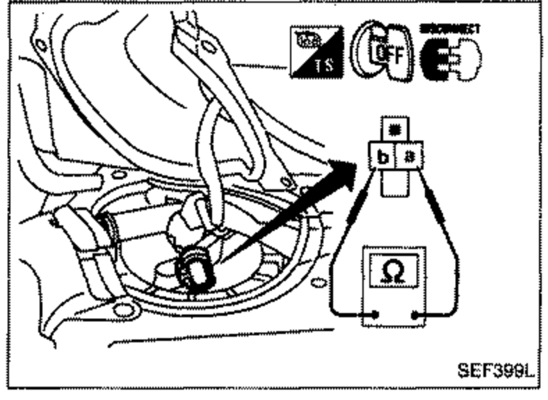 SEF399L
 - 2Disconnect fuel pump harness connector.
- 3Check continuity between terminals a and b. Continuity should exist.Continuity should exist.
FUEL PRESSURE CHECK
WARNING
a. Keep flammables away during the test.
b. For safety, the test must be completed in as short a time as possible.