
Electrical Components Inspection (Cont'd)
EF & EC-632prose procedureThrottle sensor connector illustration differs between SR20DE (SEF307L, SEF308L) and SR20DET (sub-harness connector, SEF289L).
TROUBLE DIAGNOSES
Electrical Components Inspection (Cont'd)
EXHAUST GAS SENSOR
Refer to "Diagnostic Procedure 31". (See page EF & EC-494, 590.)
THROTTLE SENSOR
- 1Disconnect throttle sensor harness connector.
- 2Make sure that resistance between terminals ⓐ and ⓑ changes when opening throttle valve manually.
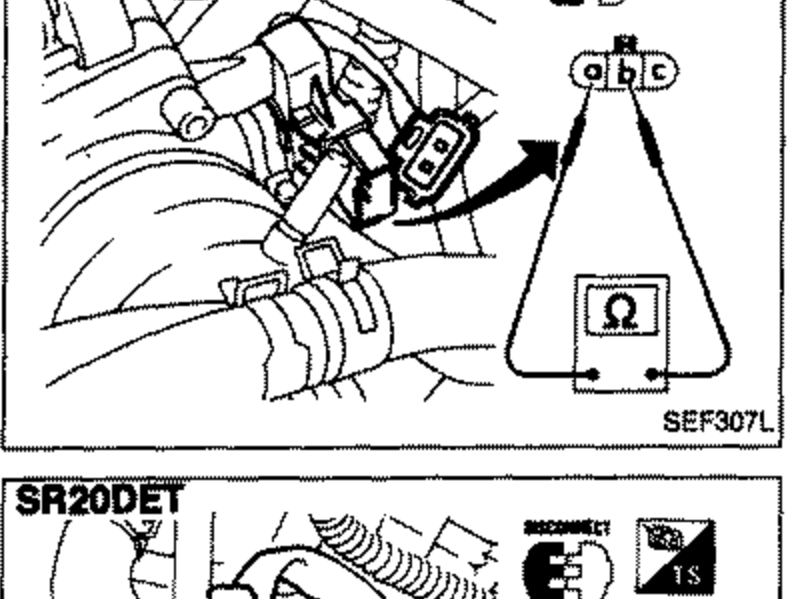 SEF307L
Throttle sensor resistance
Completely released
Resistance kΩApproximately 2
Partially released
Resistance kΩ2 - 11
Completely depressed
Resistance kΩApproximately 11
If N.G., replace throttle sensor.
Adjustment
If throttle sensor is replaced or removed, it is necessary to install in proper position, by following the procedure as shown below:
Adjustment
- 1Install throttle sensor body in throttle chamber. Do not tighten bolts. Leave bolts loose.
- 2Connect throttle sensor harness connector.
- 3Start engine and warm it up sufficiently.
- 4Perform "THROTTLE SEN ADJ" in "WORK SUPPORT" mode. Measure output voltage of throttle sensor using voltmeter.
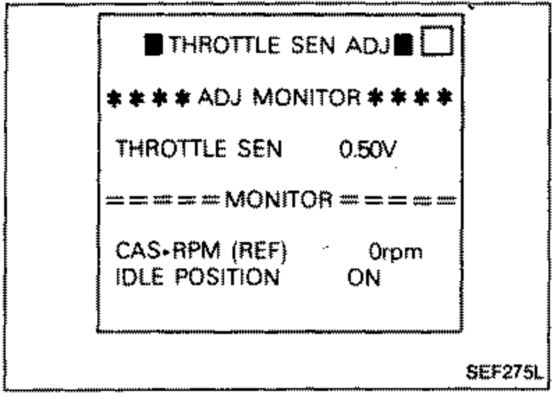 SEF275L
 - 5Adjust by rotating throttle sensor body so that output voltage is 0.45 to 0.55V.
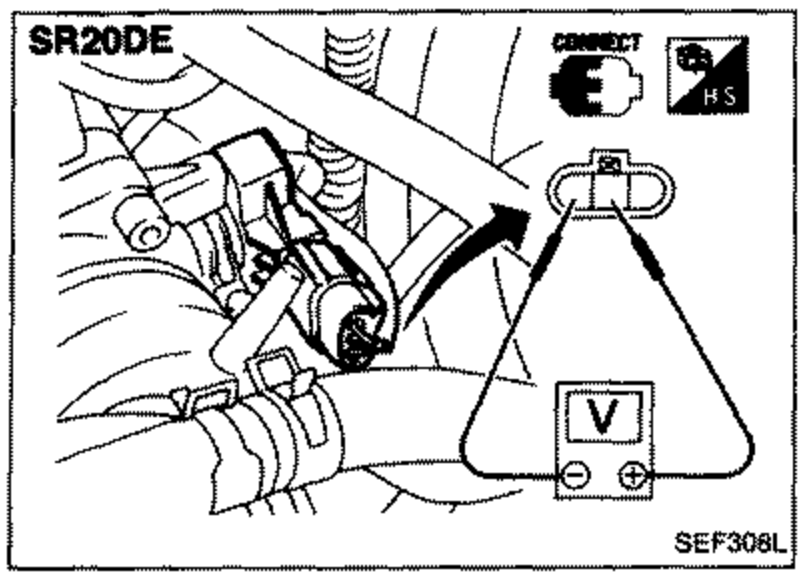 SEF308L
 - 6Tighten mounting bolts.
- 7Disconnect throttle sensor harness connector for a few seconds and then reconnect it.