
E.G.R. SYSTEM - Inspection
EF & EC-720prose procedureTerminal 12 availability differs: CD17 = No, CD20 = Yes.
Inspection
ENTIRE SYSTEM
- 1Check the vacuum hoses for loosening, flatting damage or improper connections.
- 2Warm up engine sufficiently.
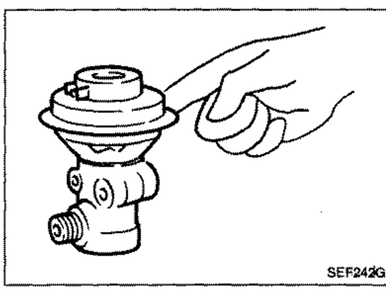
- 3Place your finger on E.G.R. control valve diaphragm to ensure that the valve functions while racing engine.Take care not to let your finger get caught between diaphragm and E.G.R. control valve body.Make sure that all harness connectors are connected securely.
 SEF243G
CONTROL UNIT OUTPUT SIGNAL
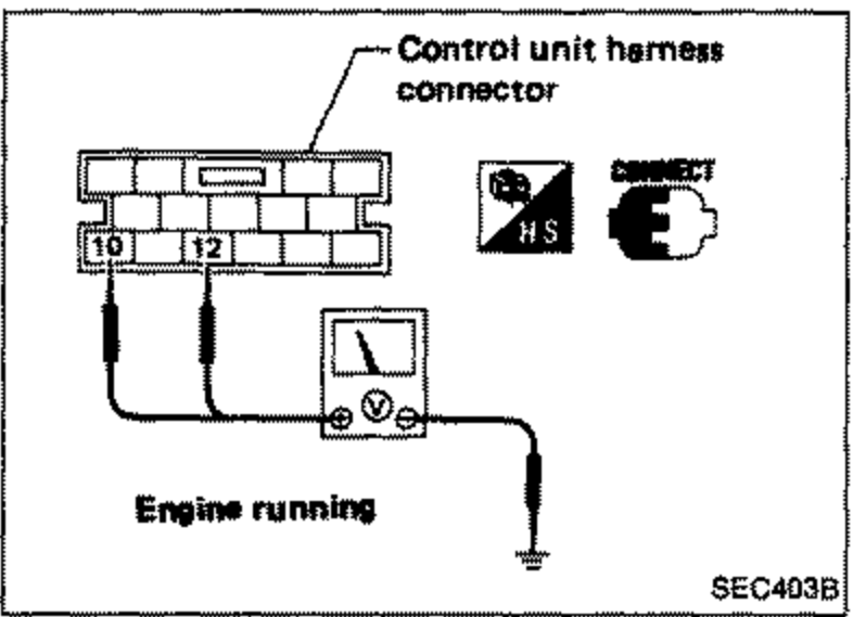
- 1Check voltage between control unit terminals 10, 12 and ground.
 SEC403B
Voltage of control unit terminals 10, 12
Below 60 (140)
Voltage of control unit terminals 10, 12Battery voltage
Above 60 (140)
Voltage of control unit terminals 10, 120V
Terminal availability
Terminal availability
10
CD17Yes
CD20Yes
12
CD17No
CD20Yes
E.G.R. CONTROL VALVE
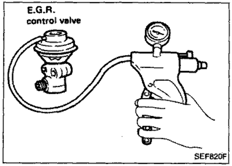
- 1Supply the E.G.R. control valve with a vacuum of 40.0 kPa (400 mbar, 300 mmHg, 11.81 inHg) using a handy vacuum pump.
 SEF820F
 - 2Place a finger on the diaphragm of the valve, and make sure that the diaphragm lifts up and down in response to the vacuum leading to the valve.Do not supply the valve with an excessively high vacuum.