
VE-TYPE INJECTION PUMP — Testing of Injection Pump (Cont'd)
EF & EC-694prose procedurePage distinguishes cold start device adjustment for CD17 (top, continued) vs CD20 (separate procedure). VE-type injection pump applies to CD diesel engines.
Testing of Injection Pump (Cont'd)
Cold start device adjustment (CD17, continued)
- 4Fully loosen cold start device lever adjusting screw, select feeler gauge whose thickness equals the specified clearance [obtained from S.D.S.: ℓ ± 0.05 mm (0.0020 in)] between idle adjusting screw and stopper, and retighten cold start device lever adjusting screw until cold start device lever contacts fast idle control lever.
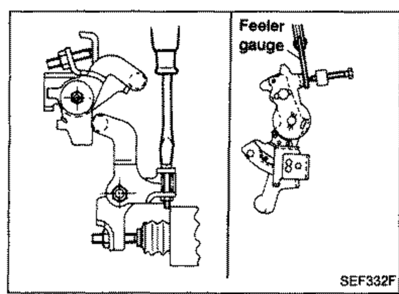 SEF332F
IMPORTANT
Temperature should be below 30°C (86°F) during adjustment.
Cold start device adjustment — CD20
IMPORTANT
Cold start device adjustment should be done after all injection pump adjustments have finished.
Temperature should be below 30°C (86°F) during adjustment.
Cold start device adjustment (CD20)
- 1Measure ambient temperature with a thermometer.
- 2At this time, ensure that speed timer piston stroke is the specified value. If not within specification, adjust timer stroke with cold start device adjusting screw.Refer to S.D.S. for speed timer piston stroke and clearance.
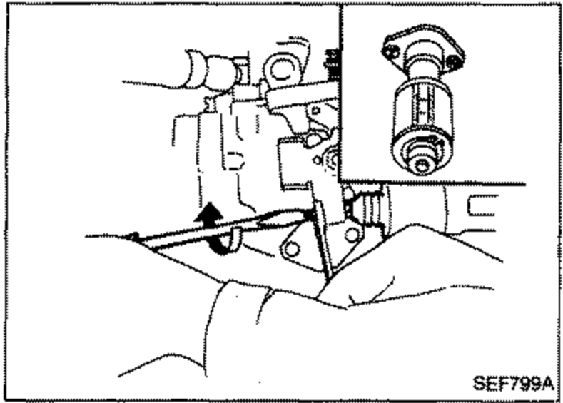 SEF799A
Preparation of cold start device
- 1Turn cold start device linkage clockwise to disengage cold start device.
- 2Set a suitable block [Thickness: about 15 mm (0.59 in)] between cold start device plunger and linkage rod.
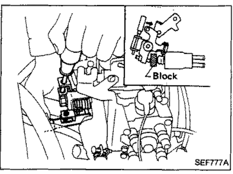 SEF777A
 - 3Insert 3.0 ± 0.05 mm (0.1181 ± 0.0020 in) feeler gauge between idle adjusting screw and control lever.
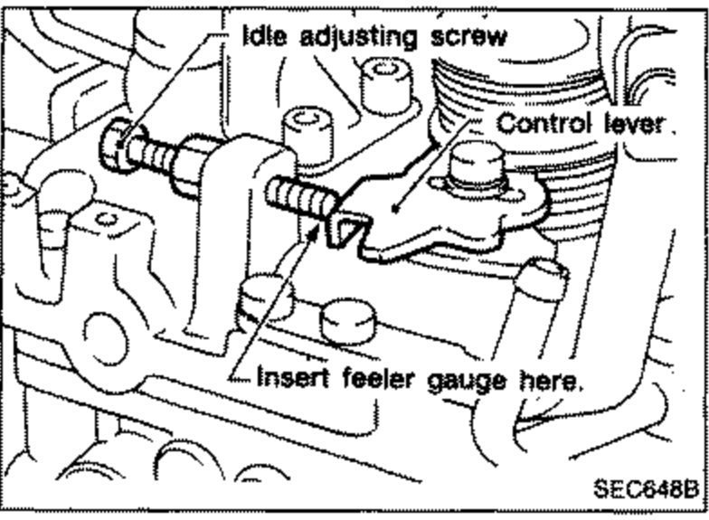 SEC648B
 - 4Adjust clearance L to 5.3 ± 0.05 mm (0.2087 ± 0.0020 in) by turning fast idle adjusting screw F.
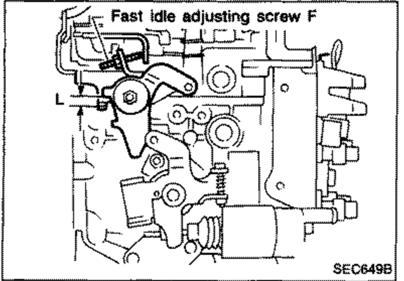 SEC649B
 - 5Tighten fast idle adjusting screw lock nut.
See also
S.D.S.