
Engine Maintenance (CD)
MA-50prose procedureCD20 diesel engine valve clearance procedure.
Manifold Nut Check
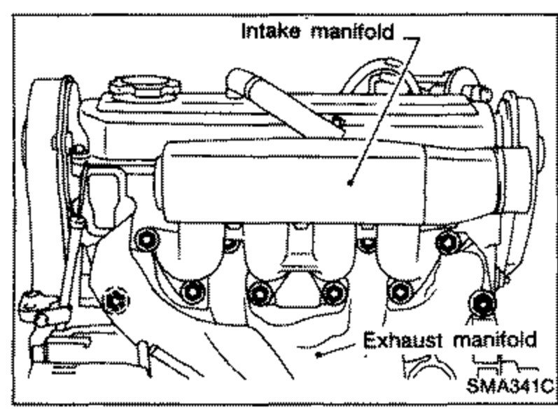
- 1Remove exhaust manifold cover.
 SMA341C
 - 2Tighten manifold bolts and nuts to the specified torque.
- 3Install exhaust manifold cover.
Valve Clearance Adjustment
Warm up engine to the normal operating temperature.
Valve Clearance Check
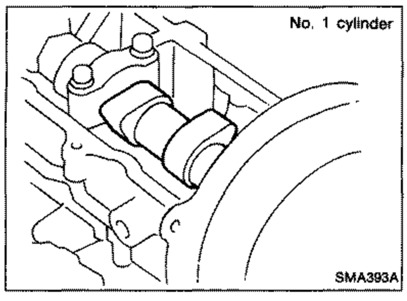
- 1Set No. 1 cylinder to T.D.C. on its compression stroke.
 SMA393A
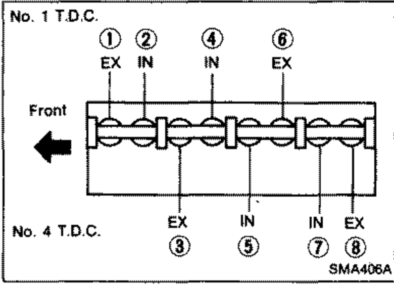
 - 2Check valve clearances of cylinders No. 1, 2, 4 and 6.
 SMA406A
 - 3Set No. 4 cylinder to T.D.C. on its compression stroke.
- 4Check valve clearances of cylinders No. 3, 5, 7 and 8.
Valve clearance (Hot)
Intake
Clearance — Unit: mm (in)0.20 - 0.30 (0.008 - 0.012)
Exhaust
Clearance — Unit: mm (in)0.40 - 0.50 (0.016 - 0.020)
Valve Clearance Adjustment
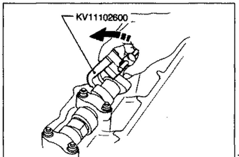
- 1Set the cylinder, whose valve clearance needs to be adjusted, to T.D.C.
 SMA480A
 - 2Turn crankshaft an additional 90 degrees clockwise from T.D.C.
- 3Set Tool or equivalent between cams on camshaft.