
Engine Lubrication System - Oil Pump (Cont'd) - Disassembly and Assembly / Installation
LC-32parts diagramSeparate torque/inset provided for 4WD models.
Oil Pump (Cont'd)
DISASSEMBLY AND ASSEMBLY
Parts DiagramFig. SLC613A

| Specification | Value |
|---|---|
| Oil pump cover bolts | 3.7 - 5.0N·m (0.38 - 0.51 kg-m, 2.7 - 3.7 ft-lb)6.4 - 7.5N·m (0.65 - 0.76 kg-m, 4.7 - 5.5 ft-lb) |
| Bolt | 16 - 19N·m (1.6 - 1.9 kg-m, 12 - 14 ft-lb) |
| Plug | 39 - 69N·m (4.0 - 7.0 kg-m, 29 - 51 ft-lb) |
| Oil strainer bolt (4WD)4WD models | 6.4 - 7.5N·m (0.65 - 0.76 kg-m, 4.7 - 5.5 ft-lb)16 - 19N·m (1.6 - 1.9 kg-m, 12 - 14 ft-lb) |
| Liquid gasket bead widthfront cover mating surface | 2.0 - 3.0mm (0.079 - 0.118 in) |
Oil pump cover bolts
3.7 - 5.0N·m (0.38 - 0.51 kg-m, 2.7 - 3.7 ft-lb)6.4 - 7.5N·m (0.65 - 0.76 kg-m, 4.7 - 5.5 ft-lb)
Bolt
16 - 19N·m (1.6 - 1.9 kg-m, 12 - 14 ft-lb)
Plug
39 - 69N·m (4.0 - 7.0 kg-m, 29 - 51 ft-lb)
Oil strainer bolt (4WD)4WD models
6.4 - 7.5N·m (0.65 - 0.76 kg-m, 4.7 - 5.5 ft-lb)16 - 19N·m (1.6 - 1.9 kg-m, 12 - 14 ft-lb)
Liquid gasket bead widthfront cover mating surface
2.0 - 3.0mm (0.079 - 0.118 in)
NOTE
Always replace oil seal and O-ring with new ones. When installing oil pump, apply engine oil to inner and outer gear. Be sure that O-rings are properly fitted.
INSTALLATION
Before installing front cover assembly, remove all traces of liquid gasket from mating surface using a scraper. Also remove traces of liquid gasket from mating surface of cylinder block.
Oil Pump - Installation
- 1Apply a continuous bead of liquid gasket to mating surface of front cover assembly. Use Genuine Liquid Gasket or equivalent.
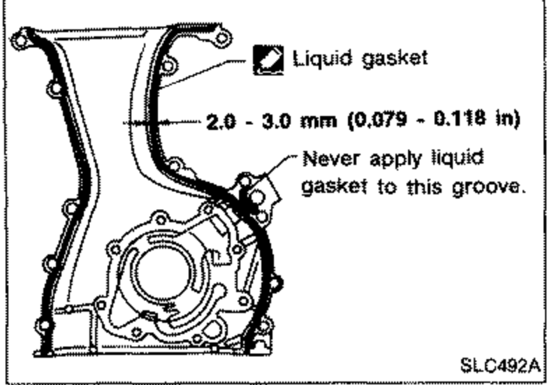 SLC492A
 - 2Installation is in reverse order of removal.