
Oil Pump
LC-12parts diagramENGINE LUBRICATION SYSTEM
Oil Pump
Parts DiagramFig. SLC497A

REGULATOR VALVE INSPECTION
- 1Visually inspect components for wear and damage.
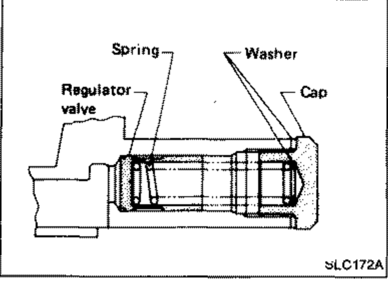 SLC172A
 - 2Check oil pressure regulator valve sliding surface and valve spring.
- 3Apply regulator valve with engine oil and check that it falls smoothly into the valve hole by its own weight.
IMPORTANT
If damaged, replace regulator valve set or oil pump assembly.
OIL PRESSURE RELIEF VALVE INSPECTION
Inspect oil pressure relief valve for movement, cracks and breaks by pushing the ball. If replacement is necessary, remove valve by prying it out with suitable tool. Install a new valve in place by tapping it.