
HOW TO FOLLOW FLOW CHART IN TROUBLE DIAGNOSES
GI-14prose procedureHOW TO FOLLOW THIS FLOW CHART
- 1Work and diagnostic procedure: Start to diagnose a problem using procedures indicated in enclosed blocks, as shown in the following example.
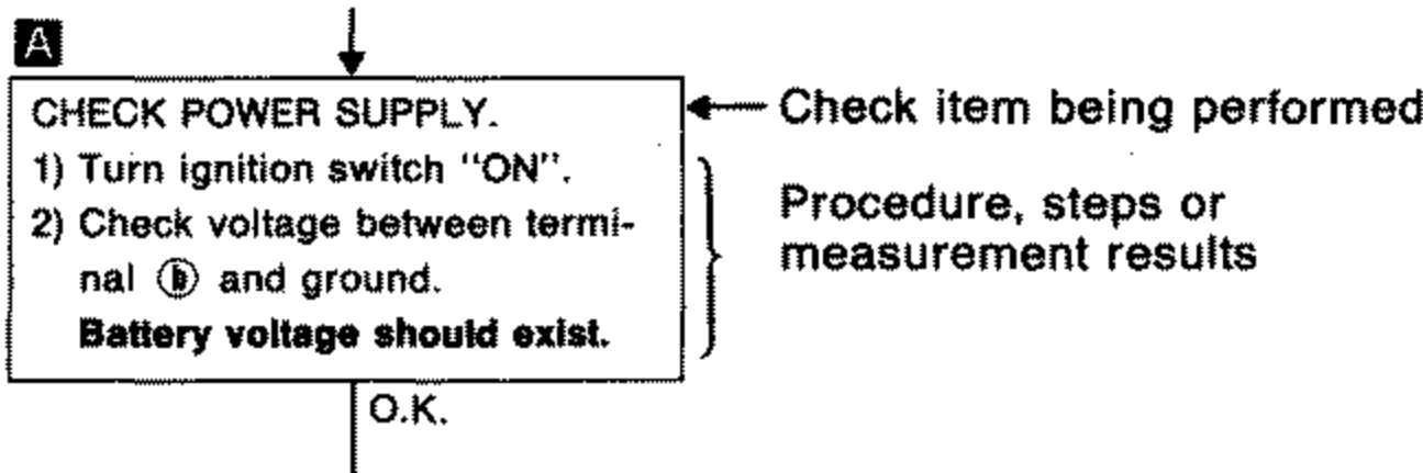
- 2Measurement results: Required results are indicated in bold type in the corresponding block, as shown below: These have the following meanings: Battery voltage → 11 - 14V or approximately 12V. Voltage: Approximately 0V → Less than 1V
- 3Cross reference of work symbols in the text and illustrations: Illustrations are provided as visual aids for work procedures. For example, symbol A indicated in the left upper portion of each illustration corresponds with the symbol in the flowchart for easy identification. More precisely, the procedure under the "CHECK POWER SUPPLY." outlined previously is indicated by an illustration A.
- 4Symbols used in illustrations: Symbols included in illustrations refer to measurements or procedures. Before diagnosing a problem, familiarize yourself with each symbol.
Direction mark
A direction mark is shown to clarify the side of connector (terminal side or harness side). Direction marks are mainly used in the illustrations indicating terminal inspection.
T.S. : View from terminal side ... T.S.
All connector symbols shown from the terminal side are enclosed by a single line.
H.S. : View from harness side ... H.S.
All connector symbols shown from the harness side are enclosed by a double line.